Application
Dense Phase Conveying for Abrasive Materials
Answer in brief
Dense phase conveying reduces erosive wear by moving abrasive material at lower velocity and higher solids concentration — it does not eliminate it. Bends, valves and acceleration zones still take concentrated impacts. Lasting designs pair material testing and velocity control with forgiving geometry, replaceable wear sections and planned inspection.
Reviewed July 26, 2026 · Updated October 8, 2026
The problem
Conveying performance, product condition and equipment life depend on the interaction between the material, gas, pipeline and operating sequence. A generic technology label is not enough to approve the duty.
Desired outcome
A predictable service life with controlled wear, stable capacity and inspection points that allow maintenance before a leak or loss of performance occurs.
Process approach
Abrasive powders remove material from pipes and fittings through repeated particle contact. Wear can contaminate product, change capacity and eventually create a leak. It should be treated as a predictable design and maintenance issue, not as an unexpected failure.
Understand the wear mechanism
Erosion depends on particle properties, impact velocity, impact angle, concentration and the target material. Scientific studies of pneumatic conveyor bends show that particle concentration can reduce specific erosion through shielding, while high velocity impacts at direction changes remain a dominant concern.
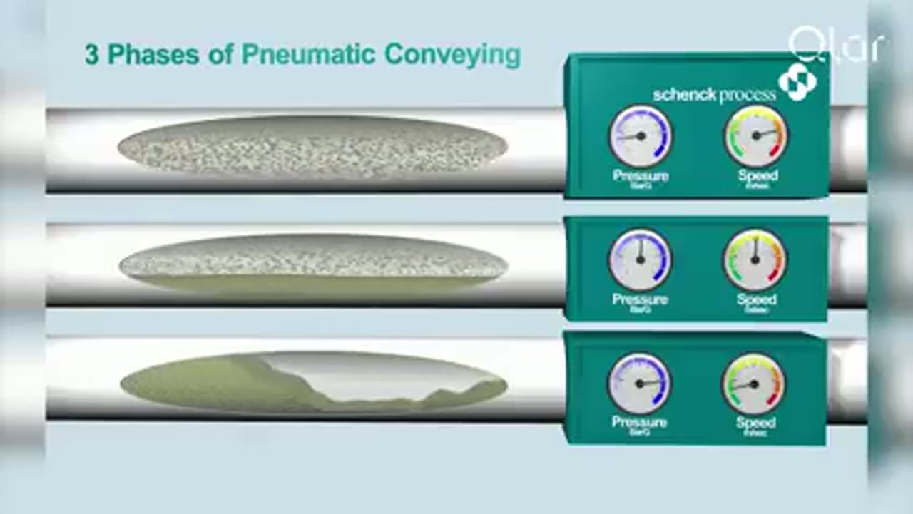
Dense phase can reduce velocity and severe impacts, but it can also increase sustained particle contact. The resulting balance depends on the flow mode. This is why a broad claim that dense phase eliminates wear is not credible.
Map every high-risk location
Review bends, tees, valves, reducers, pipe entries and acceleration zones. The outer radius of a bend often receives concentrated impacts, but the actual wear pattern depends on particle trajectory and solids loading. Access for inspection is as important as the selected wall material.
Keep the route simple. Where a direction change is necessary, consider geometry that lowers impact severity and provide a replaceable component where wear is expected. Avoid placing critical wear points where they cannot be inspected because of insulation, structural steel or other equipment.
Control velocity across the operating range
Use the minimum velocity that maintains stable transfer for the tested material and duty. Check startup, turndown and empty line conditions, not only the nominal rate. A control strategy that produces large pressure or feed swings may create periods of much higher local velocity.
Record the assumed solids loading and pressure profile. Changes in feed rate, gas supply or material bulk density can move the system away from the tested condition.
Select materials as part of a system strategy
Pipe and bend materials, liners and surface treatments should match the material and impact regime. A harder material is not automatically the best choice for every impact angle. Product contamination limits, cleanability, temperature and repair methods also affect the decision.
Plan replaceable sections and define wear limits. Inspection may use thickness measurement, visual checks or condition monitoring suited to the installation. The maintenance plan should state locations, methods, intervals and the action threshold.
Verify wear assumptions
Representative testing can compare candidate velocities, geometries and materials. During commissioning, establish baseline thickness or condition records at critical locations. Trend findings with throughput because operating hours alone do not describe the mass of abrasive solids that has passed through the system.
Review the wear basis whenever the material source, particle size, rate, route or control settings change. A system proven for one powder is not automatically proven for another abrasive duty.
Engineering visual guide
How the system behaves
These conceptual diagrams connect the operating principle, equipment internals and engineering review points. They are explanatory and not fabrication drawings or a substitute for project-specific calculations.
Engineering infographic
Source-to-destination process flow
Conceptual source-to-destination process flow for Dense Phase Conveying for Abrasive Materials; use it to structure an engineering review, not as a fabrication drawing or project-specific design.
Selection factors
Particle hardness, size, shape, density, concentration, required rate, gas velocity, solids loading, route, bend radius, bend angle, pipe and liner materials, expected operating hours, inspection method and acceptable contamination from wear.
Engineering infographic
Engineering input and decision path
Conceptual engineering input and decision path for Dense Phase Conveying for Abrasive Materials; use it to structure an engineering review, not as a fabrication drawing or project-specific design.
Common failure modes
- Treating low velocity as proof of no wear
- Tight bends in high impact locations
- Uncontrolled acceleration after a pressure vessel
- Wear hidden beneath insulation
- No replaceable section at predictable wear points
- Changing material or rate without reviewing the wear basis
Engineering infographic
Fault recovery and acceptance workflow
Conceptual fault recovery and acceptance workflow for Dense Phase Conveying for Abrasive Materials; use it to structure an engineering review, not as a fabrication drawing or project-specific design.
Partner with powderbulkvideos.com
Put a relevant technical solution in this decision path.
Connect your company and video evidence with clearly labelled visibility where engineers evaluate this material, application, industry or product.
Frequently asked questions
Why can dense phase reduce pipeline wear?
Lower particle velocity and higher solids concentration can reduce the energy and frequency of severe wall impacts. The result depends on the actual flow pattern and route.
Where does wear usually require the closest attention?
Bends, tees, valves, acceleration zones and other changes in direction deserve specific review because particle trajectories concentrate impacts there.
Can pipe material alone solve erosion?
No. Material selection helps, but velocity, bend geometry, solids concentration, particle properties, inspection and replaceable wear sections must be considered together.
Related content
Continue exploring
Move from this page to the companies, videos and technical topics that add useful context.
Companies