
Guide
Dense Phase Conveying Selection & Design Guide
Answer in brief
Choose dense-phase pneumatic conveying only after the material, flow regime, complete pipe route and acceptance limits have been tested together. A low conveying velocity on its own proves very little: stability depends on permeability, air retention, pressure gradient and route, and representative loop testing normally decides the question.
By Editorial Team · Published July 16, 2026 · Updated July 26, 2026

Sponsored visibility
Featured videos for this topic
Paid placements are clearly marked and remain separate from the editorial related-video selection.
Start with the conveying duty, not the equipment
Start with the job the system has to do. Before anyone reaches for a blow-tank catalog, define the solids-rate range, operating schedule, source and destination pressures, product-quality limits, containment requirement and restart duty.
Draw the boundary wide: Put the storage outlet, solids feeder, gas supply, conveying line, bends, receiver, filter, discharge device and controls inside one pressure and mass balance. The broader pneumatic conveying system design workflow covers the steps shared by all pneumatic systems; this guide concentrates on the dense-phase decisions.
A pressure vessel and an impressive solids-loading ratio can still produce an unstable line. The material decides the regime, not the equipment label.
Decide which flow regime is physically possible
Dense phase isn't one neat flow pattern. It is a family of non-suspension regimes — the dense-phase conveying overview maps the main equipment families and flow modes — and they behave quite differently when the line gets longer, the fines content changes or the receiver pressure rises.
Fluidized dense phase: Fine powders with sufficient air retention may move as an aerated bed or a series of soft waves at relatively low gas velocity.
Moving-bed transport: Some products travel as dunes or strands along the pipe invert while gas passes above and through the bed.
Slug or plug flow: Coarser, permeable and relatively uniform particles may form full-bore plugs separated by gas pockets, provided the plugs remain mobile and do not compact into a blockage. Review plug conveying when full-bore plugs are a credible material-specific regime rather than a generic dense-phase label.
Unstable transition: Operation between suspended flow and stable dense transport can create stationary layers, intermittent long slugs and large pressure fluctuations.
Observe the intended regime in a representative test loop. Particle-size distribution, permeability, air retention, density, shape, cohesion and moisture can move the operating boundary far enough to turn a calm test into a rather lively plant startup.
Compare dense phase with the real alternatives
Dilute phase: Suspension conveying accepts a wider range of materials, but its higher gas velocity can increase bend impact, attrition, filter load and pipeline wear. The system boundaries are compared in more detail in dense phase versus dilute phase conveying.
Mechanical conveying: Screws, belts, vibratory conveyors and enclosed chain systems can be preferable when the route is simple, very high throughput dominates or the material cannot sustain a stable pneumatic regime.
Hydraulic transport: Slurry transport changes the entire separation and product-recovery problem and is relevant only when adding and later removing a liquid is compatible with the process.
| Decision factor | Dense phase pneumatic | Dilute phase pneumatic | Mechanical conveyor |
|---|---|---|---|
| Material suitability | Restricted by permeability, air retention and stability | Broad when particles can be suspended and fed | Depends on conveyor form and route |
| Route flexibility | High, but bends and elevation consume pressure margin | High, with velocity and wear consequences | Usually constrained by conveyor geometry |
| Containment | Enclosed pressure or vacuum boundary | Enclosed pressure or vacuum boundary | Varies from open belt to fully enclosed screw or chain |
| Product stress | Often lower velocity, but plug collapse and fittings still matter | More frequent high-velocity impacts | Depends on shear, compression, transfer points and residence time |
| Design proof | Representative loop testing is normally decisive | Correlations and tests remain material-specific | Capacity and material tests depend on conveyor type |
Lower velocity is a possible benefit, not a selection method. Dense phase belongs on the shortlist only when the material, pressure gradient, feeding concept and route can sustain a controllable non-suspension regime.
Characterize the material under representative conditions
A powder sample taken straight from a fresh bag may not represent material that has sat in a humid silo for three days. Test the state the plant will actually handle.
Particle data: Record the complete particle-size distribution, fines fraction, particle shape and particle density rather than one median size.
Bulk state: Measure loose, settled and aerated bulk density because feeder capacity, blow-tank inventory and plug formation depend on the state in which the material enters the line.
Gas interaction: Permeability and de-aeration behavior help distinguish powders that can retain a fluidized state from granular solids that can sustain permeable plugs.
Handling behavior: Include cohesion, moisture sensitivity, wall friction, friability, abrasiveness, electrostatic behavior and credible foreign particles.
Test the material in the condition expected at the plant, including temperature, storage time and batch-to-batch variation.
Read the conveying characteristic correctly
Gas velocity: Superficial gas velocity is ug = Qg/A, using local actual gas flow and pipe cross-sectional area.
Solids loading: The solids-loading ratio is μ = ṁs/ṁg, using solids and gas mass flow rates in consistent units.
Boundary terms: Saltation in a horizontal line, choking in a vertical line and complete blockage describe different mechanisms and should not be used as synonyms.
The minimum of a pressure-drop curve is a useful test observation, but it is not automatically the safe lower transport boundary for every material and route.
A robust setpoint remains separated from the unstable zone and preserves margin for material variation, receiver backpressure and filter loading.
Build the pressure and gas-flow budget
Pressure components: Total required pressure includes gas friction, solids acceleration, particle-wall or plug resistance, static lift, bends, valves, feeder losses and receiver backpressure.
No single pressure-drop correlation is reliable for every dense-phase material because the dominant resistance changes with the flow mechanism.
Gas expansion: Gas expands as absolute pressure falls along a positive-pressure line, so actual volumetric flow and gas velocity rise toward the receiver.
That last point is easy to miss. The inlet can look conservative while the outlet drives attrition, receiver loading and filter duty.
Pressure margin: Compare the predicted maximum with compressor or blower capability, vessel design pressure, relief strategy and the minimum margin needed for a controlled restart.
Select the solids-feeding concept
Blow-tank sequence: A batch vessel normally fills at low pressure, isolates from the source, pressurizes, conveys through its outlet and then depressurizes before refilling.
Top-air, fluidizing-air and supplementary line-air distribution must suit the material and the required discharge pattern.
Top-discharge and bottom-discharge arrangements create different stability, residual inventory and gas-use trade-offs, so neither is universally superior.
Continuous duty: Twin vessels, lock hoppers or pressure-rated rotary feeders may be considered when the process cannot accept batch flow.
The feeding device must maintain the required pressure boundary without imposing unacceptable shear, leakage gas or pulsation on the upstream process.
Compare pressure-vessel and continuous feeding architectures
| Architecture | Principal strength | Engineering constraint | Typical review point |
|---|---|---|---|
| Single blow tank | Simple high-pressure batch transfer without a rotating pipeline feeder | Interrupted solids delivery and fill/pressurize cycle time | Batch size, residual heel and receiver surge capacity |
| Twin blow tanks | Alternating vessels can approximate continuous delivery | Sequence coordination, headroom and transfer transients | Changeover stability and pressure equalization |
| Lock hopper plus feeder | Separates high-pressure transfer from continuous metering | Additional valves, vessel volume and control states | Isolation integrity and feeder pressure differential |
| Pressure-rated rotary valve | Continuous pocket feeding for suitable granular duties | Leakage gas, clearances, wear and particle trapping | Gas balance and model-specific pressure rating |
| Screw or plug-forming feeder | Controlled solids input and possible plug formation | Shear, compaction, drive torque and seal wear | Material response and safe overload recovery |
No architecture is intrinsically dense phase: the observed pipeline regime still depends on the material, gas flow, pressure gradient and route.
Design the route, receiver and filter as one system
Pipeline geometry: Specify internal diameter, straight lengths, vertical lifts, bend radii, bend orientation, roughness, valves, flexible sections and every change in diameter.
Unnecessary bends add pressure loss, impact stress and potential buildup locations.
Receiver duty: The receiver must separate solids without excessive impact, contain the batch volume and discharge at the required downstream rate.
Filter duty: Size the filter for conveying gas, leakage gas, displaced air and cleaning pulses at the worst credible operating state.
Track filter differential pressure because a rising value increases receiver backpressure and can move the conveying line outside its validated window.
Engineering visual guide
How the system behaves
These conceptual diagrams connect the operating principle, equipment internals and engineering review points. They are explanatory and not fabrication drawings or a substitute for project-specific calculations.
Engineering infographic
Pressure vessel, gas path and receiver as one system
The pressure budget includes the feed vessel, conveying line, receiver and filter; pressure taps and gas-flow measurement are required to distinguish vessel emptying from line or receiver restriction.
Engineering infographic
System architecture and interfaces
Conceptual system architecture and interface map for Dense Phase Conveying; use it to structure an engineering review, not as a fabrication drawing or project-specific design.
Specify pipework, bends and materials of construction
Pipe bore: A diameter change alters gas velocity, solids concentration and pressure gradient, so a stepped line must be justified from the complete conveying characteristic rather than a velocity rule alone.
Bend geometry: Long-radius elbows, short-radius bends, blind tees and specialized wear bends create different impact, sliding, pressure-loss and cleanability patterns.
Construction material: Carbon steel, stainless steel, aluminum, lined pipe and hardened wear components differ in corrosion resistance, surface condition, contamination risk, impact response and inspectability.
Connections: Flanges, couplings, hoses and expansion joints must preserve alignment, pressure integrity, electrical continuity and a smooth internal product path.
For abrasive duty, define replaceable high-wear sections and thickness-monitoring points; for hygienic duty, define drainability, cleanability, material certificates and the permitted joint design.
Partner with powderbulkvideos.com
Put your expertise beside the decisions engineers are making.
Connect a relevant company profile and technical video portfolio with clearly labelled visibility on this topic.
Scale pilot data without changing the mechanism
Test record: Document material condition, pipe bore, route, bend geometry, solids rate, gas mass flow, pressure at several locations, batch sequence and observed flow regime. Record pressure signatures and the location of deposits or plug formation, not just average throughput, and repeat the trial with a credible difficult material condition.
If secondary air is used, document each injection point, its flow or control basis and its effect on product velocity.
Scale-up check: Reconcile every difference in diameter, line length, elevation, bend count, receiver pressure and vessel cycle between the pilot and the plant, and mark which behavior was directly observed and which part of the full-scale design is extrapolated.
Scale-up preserves the flow mechanism; it does not multiply capacity from one favorable run. A pressure gradient copied from a short loop can hide gas expansion, long-line instability and a plant-specific outlet-velocity limit.
Validate the upper and lower operating boundaries as well as the nominal duty point.
Machine cutaway
Inside a dense-phase pressure vessel cycle
Generic pressure-vessel cutaway showing a closed filling boundary, upper and lower conveying-gas connections, the pressurised solids volume, vent path and sealed outlet. Nozzle count, valve sequence and vessel proportions must be confirmed for the selected system.
A real plant example: conveying into a pressurized reactor
A Gericke dense-phase system weighs each batch in a sender vessel before conveying it into a reactor whose backpressure varies from 0.1 to 2 bar.
The useful lesson isn't the brand name. It is the control problem: receiver pressure is part of the conveying duty, so the system adjusts conveying pressure rather than pretending the destination stays constant. The Repco food-premix case study shows the same discipline, combining representative testing, load-cell mass tracking and destination control in one system.
Control wear, attrition and segregation
Impact locations: Bends, blind tees, receiving targets and the final line section are common high-stress zones.
Lower particle velocity can reduce impact damage, but dense-phase operation does not guarantee gentle handling when plugs accelerate, collapse or strike fittings. When product damage is the governing limit, review gentle dense-phase conveying of fragile products for the application-specific checks.
Product test: Compare particle-size distribution, fines, pellet length, bulk density or another product-specific quality measure before and after repeated conveying cycles.
Wear plan: Identify replaceable bends, inspection access, thickness-monitoring locations and the failure consequence of a worn line.
Engineering infographic
Evidence chain from material sample to plant scale
Pilot results are transferable only when material condition, measured flow regime, route geometry and plant differences remain explicit.
Instrument the operating envelope and recovery sequence
Core measurements: Record vessel pressure, line-inlet pressure, at least one intermediate pressure, receiver pressure, filter differential pressure, gas mass or standard-volume flow and transferred mass per cycle.
Correlate these signals with valve states and batch time so unstable plugs, a restricted receiver and an emptying vessel can be distinguished.
Permissives: Confirm valve position, receiver availability, gas availability and safe pressure state before each sequence transition.
Restart case: Define how a partially filled line is isolated, depressurized, inspected and restarted without exposing personnel to stored pressure or moving material. State the scenarios the system must survive: an interrupted batch, loss of conveying air and material settled in a vertical section.
Supplier scope: Require the offered controls to detect an abnormal pressure rise, stop further feeding and leave the system in a condition that can be isolated and depressurized, with defined access points and a method for confirming zero pressure before opening.
Have recovery demonstrated under an agreed scenario. Repeated purging at maximum gas flow may clear the pipe while destroying fragile material or pushing the system into a high-wear regime; the accepted method must protect people, equipment and product.
Diagnose the system from coordinated measurements
| Observed pattern | Possible mechanisms | Checks before adjustment |
|---|---|---|
| Rising vessel pressure with little transferred mass | Restricted outlet, compacted product, closed path or inadequate discharge aeration | Valve states, vessel mass, outlet pressure and material condition |
| Large repetitive pressure peaks | Long plugs, unstable transition, insufficient line air or geometric restriction | Intermediate pressure timing, gas mass flow and plug arrival at the receiver |
| Stable inlet pressure but rising receiver pressure | Filter loading, receiver vent restriction or discharge backup | Filter differential pressure, receiver level and displaced-air path |
| Increasing gas use per tonne | Leakage, worn seals, changed material, longer clear phase or control drift | Standard gas flow, batch mass, cycle states and pressure decay |
| Higher fines or bend wear | Outlet acceleration, unstable plugs, excessive line air or unfavorable fittings | Local velocity, pressure profile, product samples and wear inspection |
These patterns identify investigation paths, not automatic diagnoses; confirm the cause before changing gas flow, pressure or valve timing.
Evaluate energy and lifecycle on a delivered-mass basis
Energy boundary: Include compressor or blower power, air drying, cooling, receiver filtration, vessel sequencing and idle or purge gas.
Compare systems using measured energy per mass delivered at the required product quality and availability, not installed motor power alone.
Lifecycle boundary: Include filters, valve seals, bends, pipe inspection, compressor service, cleaning time, product loss and the consequence of an unplanned blocked line.
A lower-velocity system can reduce some wear mechanisms while adding pressure-vessel, valve and compressed-air maintenance duties.
Complete the pressure, dust and process-safety review
Dust hazard: Use material-specific explosibility and ignition data in the applicable dust-hazard or explosion-risk assessment.
Bonding, grounding, explosion protection, isolation and venting must be selected for the actual equipment arrangement and jurisdiction.
Pressure boundary: Treat the blow tank, connected piping, valves and safety accessories under the applicable pressure-equipment rules.
Normal conveying performance does not mean that a rotary valve or another component performs a certified explosion-isolation function.
Engineering infographic
Read the complete batch pressure signature
Vessel and downstream line pressures should be correlated with mass, gas flow, filter differential pressure and valve states throughout fill, pressurise, convey, clear and depressurise.
Define factory and site acceptance before purchase
Test material: Use a representative batch, including the most difficult credible condition rather than an easily conveyed substitute, and record the exact batch and condition used.
Operating matrix: Repeat minimum, normal and maximum throughput cases and include startup, normal stop, emergency interruption and an interrupted-cycle restart where the process requires it.
Measured acceptance: Agree capacity, pressure margin, gas use per mass transferred, product-quality change, receiver and filter behavior, valve sequencing, residue, containment or emissions checks and repeatability. Separate measured results from model predictions in the final test record.
Handover: Deliver the validated operating window, alarm and trip responses, inspection points, acceptable wear observations and the changes that trigger a new engineering review. Reliability depends on preserving the relationship between material, air, feeding and route after commissioning.
A good acceptance test feels slightly unforgiving. It uses the awkward material condition, the slow refill, the dirty filter case and the interrupted batch that everyone would prefer to postpone until after handover.
Supplier specification checklist
- Material sample definition and property ranges.
- Required flow regime and the test results used to identify it.
- Mass-flow range, batch size and cycle requirement.
- Pipeline route, pressure budget and gas-flow basis.
- Feeder, receiver, filter and discharge interfaces.
- Instrumentation, permissives and blockage-recovery sequence.
- Wear, cleaning, containment and product-quality limits.
- FAT, SAT and repeatable acceptance measurements.
Approach the dense-phase conveying supplier shortlist only after the duty sheet and acceptance matrix are defined.
Engineering infographic
Engineering design workflow
Conceptual engineering design workflow for Dense Phase Conveying; use it to structure an engineering review, not as a fabrication drawing or project-specific design.
Engineering infographic
Verification and acceptance checklist
Conceptual verification and acceptance checklist for Dense Phase Conveying; use it to structure an engineering review, not as a fabrication drawing or project-specific design.
Sources and further reading
- Pan: Material properties and flow modes in pneumatic conveying
- Jones and Williams: Predicting pneumatic-conveying flow modes
- Jones et al.: Particle-size-distribution screening for dense-phase potential
- Pan et al.: Scale-up and operating boundaries for slug flow
- Wypych and Yi: Minimum transport boundaries and unstable flow
- Kalman et al.: Bend design and particle attrition
- VDI 2329: Pneumatic conveying fundamentals and components
- AIChE: Dilute or dense phase pneumatic conveying?
- HSE HSG103: Safe handling of combustible dusts
- Gericke case study: dense-phase conveying into a pressurized reaction vessel
Frequently asked questions
Can every powder be conveyed in dense phase?
No. Stable dense-phase transport depends on particle-size distribution, permeability, air retention, cohesion, moisture, route and pressure gradient, so representative testing is normally required.
Is high pressure the same as dense phase conveying?
No. High pressure describes the gas-supply condition, while dense phase describes a non-suspension flow regime that the material and operating point must actually sustain.
When is dilute phase the better choice?
Dilute phase can be preferable when the material cannot sustain stable non-suspension flow, the route and duty are modest, or the additional pressure-vessel and control complexity of dense phase is not justified.
How should dense-phase conveying be scaled up?
Scale-up must preserve the observed flow mechanism and reconcile changes in pipe bore, route, bends, elevation, gas expansion, receiver pressure, vessel cycle and material condition.
Which measurements are essential during commissioning?
Record vessel, line and receiver pressures, gas mass or standard-volume flow, filter differential pressure, valve states, transferred mass, cycle time and product-quality results at minimum, normal, maximum and restart duties.
How is dense-phase energy use compared fairly?
Compare measured energy per mass delivered at the required product quality and availability, including compressor or blower power, air treatment, purge gas, filtration and cycle losses.
Related content
Continue exploring
Move from this page to the companies, videos and technical topics that add useful context.
Companies


Videos

Hosokawa Solids Solutions GmbH
Hosokawa Solids Solutions: Solids Puls Pneu Conveying System
Hosokawa Solids presents the Solids Puls Pneu plug-conveying system with bypass, impulse-valve and relay-station components.
Total reach: 70,229
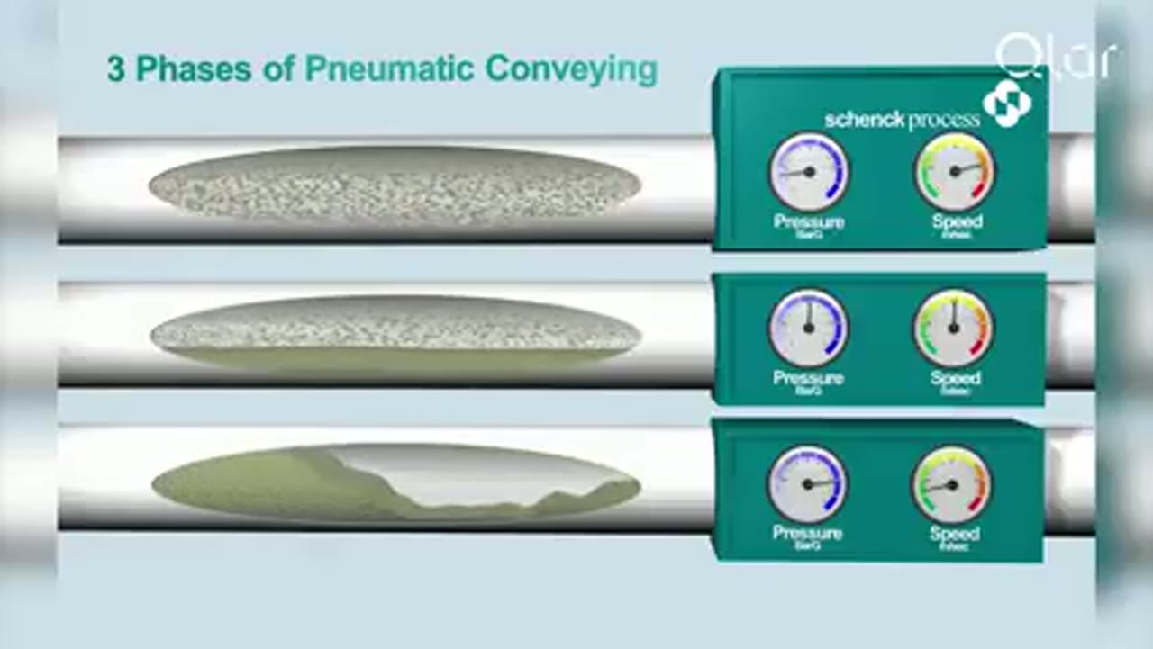
Qlar
Pneumatic Conveying Explained: The 3 Key Phases of Dense Phase Conveying
Qlar explains the three phases of dense phase pneumatic conveying and where each one fits when powders, granules and bulk solids have to move without being damaged.
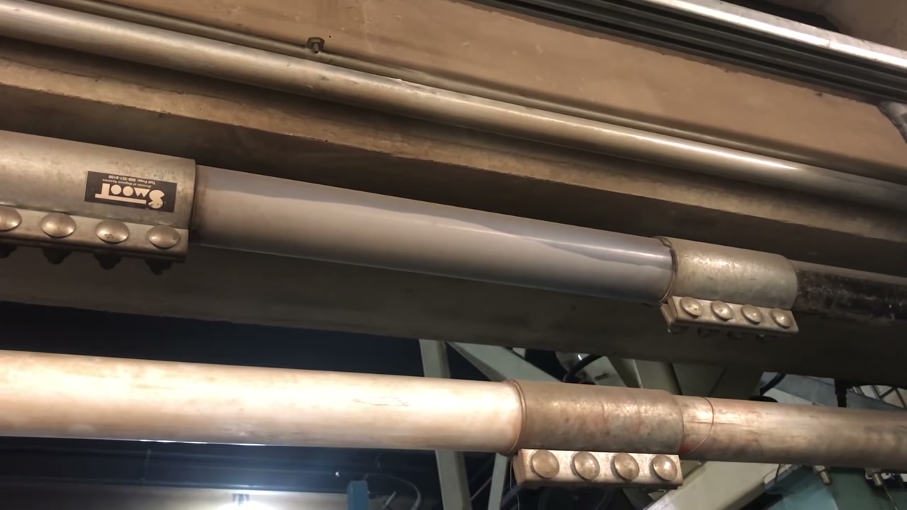
Magnum Systems
Dense Phase Conveying in the Test Laboratory
Magnum Systems shows dense phase pneumatic conveying running in its test laboratory in Kansas City.
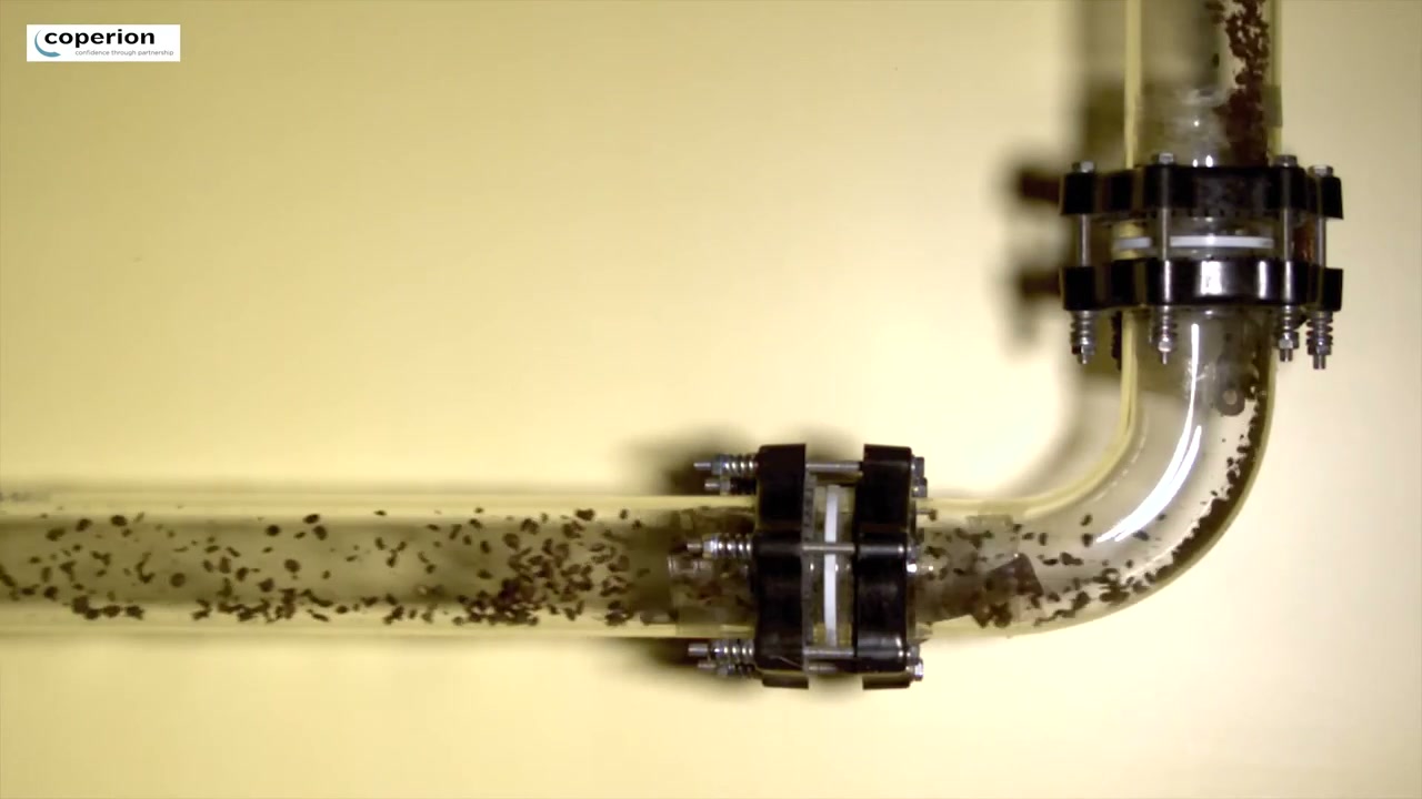
Coperion
Dense Phase Conveying of Coffee Beans
Coperion shows dense phase conveying applied to coffee beans, where the point of the method is to move a fragile product without damaging it.
Total reach: 7,829
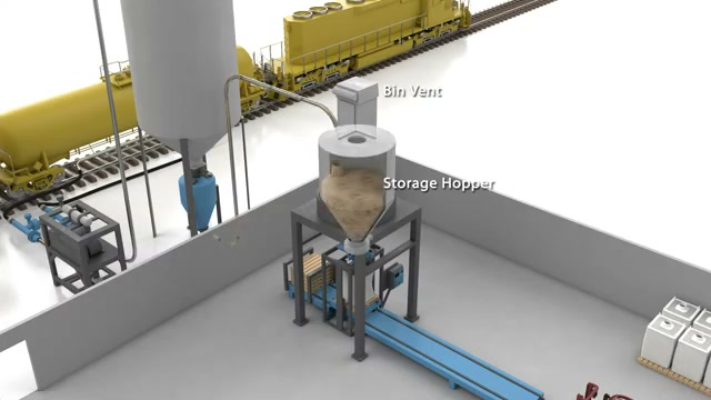
Magnum Systems
Dense Phase Conveying Process Flow Animation
Magnum Systems shows in a short animation how material travels through a dense phase line in slugs rather than as a continuous stream.
Total reach: 1,679

Coperion
E-finity Continuous Dense Phase Conveying
Coperion presents E-finity, a continuous dense phase conveying system for fragile granular and pelleted materials that monitors pressure and corrects the airflow during the run.
Total reach: 1,789