
Comparison
Vacuum Conveying vs Positive Pressure Conveying
Answer in brief
Vacuum conveying is usually the stronger starting point when powder must be drawn from several pickup points to one receiver and inward air leakage is preferable at open interfaces.
Positive-pressure conveying comes into play when one source must feed several destinations or the route and duty demand a different pressure envelope. Neither arrangement is inherently superior: the choice has to be tested against the material, route, containment objective, receiver design and operating sequence.
By Editorial Team · Published July 17, 2026 · Updated July 26, 2026

Sponsored visibility
Featured videos for this topic
Paid placements are clearly marked and remain separate from the editorial related-video selection.
Vacuum and positive-pressure conveying both use moving air to transport bulk solids through pipework, but they place the conveying line on opposite sides of atmospheric pressure.
That one distinction changes how material enters the line, where air can leak, how the receiver is separated from the air stream and how the system responds when a seal or connection is opened. It is a process-layout decision, not simply a choice between two air movers.
This comparison asks the same questions of both technologies: source and destination topology, material behavior, route, containment, filtration, controls, cleaning, maintenance and acceptance testing.
The practical difference is system topology
In a vacuum arrangement, the conveying line sits below the surrounding atmospheric pressure while material is being transported. Air and product are drawn toward a receiver, where the solids must be separated before the conveying air reaches the vacuum source.
This layout naturally supports duties in which several pickup points feed a common destination, provided the selected valves, line routing and control sequence can isolate the active source.
In a positive-pressure arrangement, the conveying gas is introduced upstream and pushes material toward the receiving side. Engineers commonly evaluate this topology where one source supplies more than one destination, or where route and duty make a pressure-driven arrangement worth considering.
The downstream receivers, filters, diverters and discharge devices must all suit the actual pressure and flow conditions; the label “positive pressure” does not resolve those interfaces by itself.
The first drawing for a selection review should therefore be a real process map. Mark every source, destination, vertical lift, bend, flexible connection, isolation point, receiver and vent path. A straight-line distance or a nominal pipe diameter cannot describe the full duty.
Decision matrix
| Selection question | Vacuum conveying | Positive-pressure conveying |
|---|---|---|
| Typical topology to investigate | Several pickup locations leading to one receiver | One source distributing toward one or several destinations |
| Leakage direction at an imperfect connection | Air tends to enter the line while it remains under vacuum | Air and potentially product may move outward from a pressurized boundary |
| Material entry | Pickup design must admit product and conveying air in a stable proportion | The feed interface must introduce solids into the pressurized gas stream without uncontrolled leakage |
| Receiving end | Receiver separates product from air and protects the vacuum source | Each destination needs suitable separation, venting, isolation and discharge |
| Primary project question | Can the required pickups, containment boundary and receiver cycle operate reliably? | Can the source, route, destinations and pressure-rated interfaces operate as one controlled system? |
| Testing required | Representative material testing and a documented trial of the complete operating cycle |
The matrix defines questions, not a universal winner. A short positive-pressure line may be appropriate, and a vacuum system may serve a demanding route, when the complete design and test results support it.
Start with the powder, not the blower
Bulk density, particle size distribution, cohesion, moisture, permeability, abrasion, fragility and electrostatic behavior all influence pneumatic transfer. The condition at pickup also matters. Powder discharged freely from a hopper does not enter a line in the same way as compacted material drawn from a bag, drum or pile through a suction lance.
Define acceptable product condition at the destination before discussing conveying velocity or cycle time. If attrition, segregation, temperature rise, contamination or residual material matters, those outcomes belong in the test plan. Reaching a mass rate is not sufficient when the transferred product no longer meets the process requirement.
Use representative samples and record their condition. A result obtained with one dry, free-flowing batch should not be extended to a wetter, more cohesive or differently aerated batch without review. Where variation is credible, the test envelope should include it.
Containment is about every interface
Vacuum is often attractive where inward leakage at a pickup connection supports the containment objective. That advantage has boundaries. Dust can still be released during bag opening, receiver discharge, filter servicing, hose disconnection, sampling or cleaning. A blocked filter or an open bypass can also change the pressure condition that operators expect.
Positive-pressure conveying requires particular attention to outward leakage paths because the line operates above its surroundings. Feed devices, couplings, diverters, receiver seals and discharge arrangements must be reviewed as pressure-boundary interfaces. This does not make the technology unsuitable; it means containment must be engineered and verified at the complete system level.
For either arrangement, map normal work and interventions. Show who connects the source, how residual powder is contained, how filters are removed, where displaced air goes and what happens if the destination cannot accept material. The relevant exposure and combustible-dust requirements depend on the powder, task and jurisdiction and cannot be inferred from the conveying principle.
Partner with powderbulkvideos.com
Put your expertise beside the decisions engineers are making.
Connect a relevant company profile and technical video portfolio with clearly labelled visibility on this topic.
Feeding, separation and filtration decide stability
A conveying line cannot compensate indefinitely for unstable material presentation. In vacuum pickup, excessive air can limit solids loading while insufficient air can leave product in the line. In positive-pressure service, the selected feed interface must meter material into the gas stream while controlling leakage across the pressure difference.
In both cases, the upstream hopper and downstream process must be included in the design basis; the wider process context is covered under pneumatic conveying.
At the receiving end, product must be separated from conveying air without unacceptable carryover or filter loading. Filter area, media, cleaning sequence and access need to match the actual dust duty and cleaning regime.
Where filtration and displaced-air handling call for a broader assessment, dust collection and air pollution control becomes part of the design basis. Receiver discharge must also fit the conveying cycle: a batch receiver that cannot empty before the next cycle will constrain the entire system regardless of nominal blower capability.
Controls must describe abnormal states
A useful control narrative begins before material enters the pipe. It defines source selection, pickup permission, destination availability, air-mover start, feed initiation, receiver level logic, filter cleaning and discharge. It also explains how the system reaches a known empty or safely stopped state.
Then add credible faults: loss of air movement, blocked line, high filter differential pressure, incomplete receiver discharge, wrong valve position, destination high level and loss of utilities.
State which signal detects each condition, what the automatic response is and what an operator must verify before restart. Pressure, airflow, drive state, valve feedback and receiver level can each reveal different problems, but the appropriate instruments depend on the final design.
Cleaning and maintenance change the comparison
Cleaning requirements should be defined as an operating method, not as an adjective. Identify whether the route is dedicated, dry-cleaned, wet-cleaned or dismantled; which components retain powder; and how cleanliness is inspected or verified. Long pipe runs, filters, flexible connections, diverters and discharge devices deserve explicit attention.
Maintenance access differs with the architecture. A vacuum system concentrates important separation and filtration functions at its receiver, while a distributing positive-pressure system may repeat receiving interfaces at several destinations. The project review should compare the real number and location of service points, not assume that one principle is automatically simpler.
Confirm performance on your own powder
A Volkmann suction lance is an example of vacuum powder pickup, and the Powder Process-Solutions Pressure Dilute Phase system is an example of a positive-pressure arrangement. Coperion ingredient-transfer systems are further examples of pneumatic handling.
Capacity, product quality and suitability depend on the powder and the route; confirm them with a trial on your product. Throughput, conveying velocity, pressure, cleaning result and safety classification belong in the supplier’s written proposal for your duty.
The Volkmann company profile and Coperion company profile give more detail on both suppliers.
Engineering visual guide
How the system behaves
These conceptual diagrams connect the operating principle, equipment internals and engineering review points. They are explanatory and not fabrication drawings or a substitute for project-specific calculations.
Engineering infographic
Side-by-side operating principles
Conceptual side-by-side operating schematic for Pneumatic Conveying; use it to structure an engineering review, not as a fabrication drawing or project-specific design.
A defensible selection workflow
- Define every source, destination and operating case.
- Characterize representative material and meaningful variation.
- Set product-quality, containment, cleaning and safety objectives.
- Map the actual route, interfaces, utilities and available access.
- Ask suppliers to declare assumptions, exclusions and battery limits.
- Test the proposed pickup, line and receiving cycle with representative material.
- Record measurable acceptance criteria and fault-recovery behavior.
- Preserve the tested configuration as the commissioning baseline.
The final decision should explain why the selected pressure regime fits the documented duty and which uncertainties remain. A qualified project team must still confirm pressure ratings, hazard controls, local requirements and the exact supplier documentation for the delivered configuration.
Engineering infographic
Selection envelope
Conceptual selection envelope for Pneumatic Conveying; use it to structure an engineering review, not as a fabrication drawing or project-specific design.
Engineering infographic
Failure and safety comparison
Conceptual failure and safety comparison for Pneumatic Conveying; use it to structure an engineering review, not as a fabrication drawing or project-specific design.
Frequently asked questions
When is vacuum conveying usually the better starting point?
When several pickup locations feed one receiver and inward leakage at open interfaces supports the containment objective. The actual route, powder behavior, receiver cycle and cleaning method still require verification.
When should positive-pressure conveying be evaluated?
When one source must supply one or several destinations, or when the route and duty justify a pressure-driven arrangement. Feed, diverter, receiver, filtration and discharge interfaces must suit the complete pressure envelope.
Does vacuum conveying guarantee dust-free operation?
No. Vacuum can make the leakage direction favorable at some connections, but dust may still escape during charging, discharge, filter service, disconnection, cleaning or an abnormal condition.
Can a supplier video prove that a powder will convey?
No. Capacity, product quality, cleanability and safety compliance depend on the material and the route. Confirm them with a trial on your product in the planned configuration.
What should a representative conveying trial record?
Material condition, tested route and configuration, mass transferred, cycle behavior, pressure and airflow where relevant, filter condition, residual material, product observations, discharge performance and restart after a controlled interruption.
Related content
Continue exploring
Move from this page to the companies, videos and technical topics that add useful context.
Companies


Videos

Hosokawa Solids Solutions GmbH
Hosokawa Solids Solutions: Solids Puls Pneu Conveying System
Hosokawa Solids presents the Solids Puls Pneu plug-conveying system with bypass, impulse-valve and relay-station components.
Total reach: 70,221

HS Umformtechnik GmbH
HS Umformtechnik Company Video
HS Umformtechnik presents large-radius pipe bends, pipe couplings and branch pipes for pneumatic conveying systems.
Total reach: 6,262
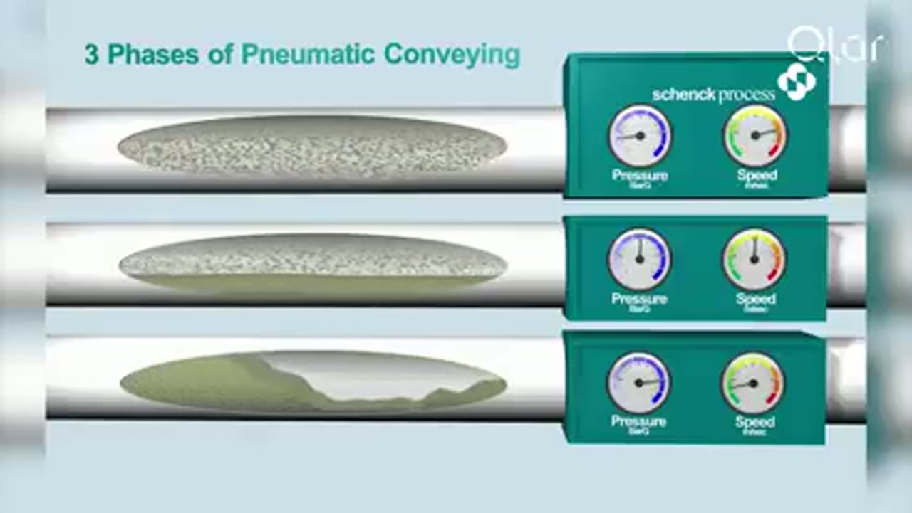
Qlar
Pneumatic Conveying Explained: The 3 Key Phases of Dense Phase Conveying
Qlar explains the three phases of dense phase pneumatic conveying and where each one fits when powders, granules and bulk solids have to move without being damaged.

VAC-U-MAX
VAC-U-MAX: 10 Critical Design Factors to Consider When Designing Vacuum Conveying Systems
VAC-U-MAX presents ten design factors for vacuum conveying, including pickup, material behavior, route, receiver, filtration, discharge and controls.
Total reach: 10,990

VAC-U-MAX
VAC-U-MAX: Signature Series Packaged Vacuum Conveying Systems
With over 65 years of experience in pneumatic conveying and more than 10,000 powders and granular materials handled, VAC-U-MAX packages its Signature Series vacuum conveying systems as complete units: receiver, UL-listed controls, convey hose, filters, and vacuum producer.
Total reach: 10,588
Powder Process-Solutions
Pressure Dilute Phase
The Powder Process-Solutions animation shows a positive-pressure dilute-phase arrangement in which a gas stream pushes suspended material through the conveying line toward the receiver.
Total reach: 92,214