
Technology guide
Pneumatic Conveying
Answer in brief
Pneumatic conveying moves powders, granules, and pellets through a closed pipeline using air or another gas. A complete system combines controlled feeding, a pressure or vacuum source, the pipeline, a receiver, filtration, discharge equipment, instrumentation, and safety measures. Which arrangement fits depends on bulk solid behavior, capacity, route, product quality, containment, cleaning, and dust hazards.
By Editorial Team · Reviewed July 14, 2026 · Updated July 26, 2026

Sponsored visibility
Featured Pneumatic Conveying videos
Paid placements are clearly marked and remain separate from the editorial related-video selection.
A pneumatic conveying line is a coordinated process system. The air mover cannot be selected independently from the feeder, pipe, receiver, filter, and discharge equipment. A restriction or poor control choice in any one part can limit capacity, damage product, or cause unstable operation.
How pneumatic conveying works
Air or another gas creates a pressure difference along a pipe. Material enters at a controlled rate, accelerates into the moving gas, travels through the route, and separates from the gas at the destination. The receiver retains the solids while the conveying gas passes through filtration and leaves the system or returns through a closed loop.
The transport behavior is a gas and solids interaction. Particle size, density, shape, cohesion, moisture, permeability, and air retention influence how the bulk solid moves. Pipe diameter, bends, vertical lift, pressure, and gas velocity act on the same flow. This is why a material name and desired capacity do not provide enough information for design.
Engineering infographic
Operating sequence
Conceptual operating sequence for Pneumatic Conveying; use it to structure an engineering review, not as a fabrication drawing or project-specific design.
Main conveying regimes
The regimes differ in solids concentration and gas velocity. AIChE's practical comparison of dilute and dense phase conveying and a recent review in Particuology examine the trade-offs summarized below.
Dilute phase conveying
Dilute phase uses enough gas velocity to keep most particles suspended. It is the most broadly applicable regime and often supports continuous operation. Higher velocity can increase wear and product attrition, so the route and material must be assessed together.
Dense phase conveying
Dense phase moves a greater concentration of solids at lower velocity. The flow can appear as strands, dunes, slugs, plugs, or a fluidized mass. Dense phase can protect fragile material and reduce wear, but not every powder forms a stable dense regime.
Intermediate and unstable flow
Operating between established regimes can produce saltation, deposits, pressure fluctuation, and intermittent movement. The lowest pressure condition is not necessarily the most reliable one. A design needs a stable operating window that covers startup, normal duty, turndown, and shutdown.
Pressure and vacuum arrangements
A pressure system places the air mover before the material pickup and pushes toward the destination. It can suit longer routes and several destinations. A vacuum system places the air mover after the receiver and draws material from one or more pickup points. Inward leakage can support dust containment at the source.
Pressure and vacuum do not define the conveying phase. Both dense and dilute systems can use a suitable pressure or vacuum arrangement. The choice depends on source access, destination pressure, distance, filtration, leakage direction, discharge method, and maintenance access.
Core system components
| Component | Primary function | Important design questions |
|---|---|---|
| Feed device | Introduces solids at a controlled rate | Can it meter the material and limit pressure leakage |
| Air mover | Creates gas flow and pressure difference | Does it deliver the required flow on the actual system curve |
| Pipeline | Contains and guides gas and solids | Are diameter, bends, wear, supports, and access suitable |
| Receiver | Separates solids from conveying gas | Can it accept both solids and gas at peak duty |
| Filter | Retains fine material | Are filter area, cleaning, containment, and differential pressure monitoring adequate |
| Discharge device | Transfers solids to the next process | Can it discharge without disturbing receiver pressure or downstream duty |
| Controls | Coordinates sequence and protects operation | Are permissives, alarms, trends, and recovery logic defined |
Material properties that matter
- Particle size distribution and fine content.
- Particle and bulk density.
- Particle shape and surface condition.
- Cohesion, permeability, and air retention.
- Moisture and hygroscopic behavior.
- Abrasion and attrition sensitivity.
- Temperature and chemical compatibility.
- Combustibility and electrostatic behavior.
Geldart classification can support early screening of fluidization behavior, but research reviewing 50 years of the classification confirms that its boundaries do not replace conveying trials. Powders near a boundary can respond differently because of fine content, permeability, or deaeration.
Benefits and limits
A closed pipeline can provide flexible routing, dust containment, automation, and fewer exposed moving parts than some mechanical alternatives. It can move material vertically and around existing plant structure. The same flexibility can hide poor design because the pipe appears simple while solids behavior remains complex.
Potential problems include insufficient capacity, plugging, buildup, filter restriction, particle degradation, segregation, wear, excessive energy demand, and electrostatic charging. These risks are managed through material data, appropriate testing, sound geometry, stable feeding, instrumentation, and operating procedures.
Selection sequence
- Define the material range and collect representative samples.
- Map the complete route and all operating cases.
- Set capacity and product quality acceptance criteria.
- Define hygiene, containment, and safety requirements.
- Screen dense, dilute, pressure, and vacuum concepts.
- Test uncertain materials and scale the selected regime.
- Design feeding, pipework, receiving, filtration, and controls together.
- Commission against the measurable operating envelope described below.
Engineering infographic
Functional zones and interfaces
Conceptual functional zone schematic for Pneumatic Conveying; use it to structure an engineering review, not as a fabrication drawing or project-specific design.
Turn the route into a pressure budget
The available pressure difference is consumed by gas flow through straight pipe, bends and fittings; acceleration and elevation of solids; the feed interface; and the receiver and filter. These contributions change with solids rate and gas density. A design review should show where pressure is expected to be used and which measurement will reveal a deviation. A single pressure value at the air mover cannot identify a blocked pickup, restricted filter or unstable section of pipe.
Route geometry should be based on an installed path, not a straight-line distance. Include vertical lifts, flexible connections, diverters, expansions and the spacing between disturbances. Provide supports for pipe weight and dynamic loads, access to likely deposition points and replaceable protection where wear is expected.
Design normal and abnormal sequences together
Startup establishes gas flow before uncontrolled solids entry. Shutdown stops feed, clears the line only as far as the material and process allow, and leaves receivers and filters in a known state. Loss of power, a full destination, high filter differential pressure or a failed valve each need a defined response. The safe response may be different from the fastest way to restore production.
Recovery depends on what remains in the pipe. A cohesive deposit may not move when full air is restored, while a fragile product can be damaged by repeated high-velocity clearing. Instrumentation should help operators distinguish insufficient gas, excessive feed, receiver restriction and material buildup before they intervene.
Commission the operating envelope
Acceptance should cover minimum, normal and maximum rate with representative material. Record gas flow where available, pressure at useful locations, feeder output, filter differential pressure, receiver level behavior and product condition. Include a planned stop and restart, a change of destination where relevant, and the difficult material condition identified during design.
Retain the pressure and cycle-time signatures as the healthy baseline. They allow later maintenance teams to separate gradual filter restriction, increasing leakage, pipe buildup and a changed product from an undersized air mover. Review the design when the route, material supplier, production rate, filter media or control sequence changes.
Safety and combustible dust
The pipeline can disperse combustible material and connect several vessels. A hazard assessment should address ignition, electrostatic discharge, frictional heating, fire propagation, explosion pressure, and transfer between connected equipment.
HSE guidance on dust explosions identifies pressure monitoring, adequate air removal at receivers, and level detection as important safeguards; the OSHA technical manual chapter on combustible dusts covers the wider hazard assessment. The final protection concept depends on the dust properties, equipment, process, and jurisdiction.
How to select Pneumatic Conveying
- Define the powder or bulk solid and its relevant physical and safety data.
- State the required transfer rate, operating schedule and acceptable residual material.
- Map horizontal distance, vertical lift, bends, pickup points and destinations.
- Define product degradation, wear, contamination and containment limits.
- Record available utilities, filtration, controls, cleaning and maintenance access.
Partner with powderbulkvideos.com
Place your video in the engineering context buyers are researching.
Use a relevant company profile and technical video to demonstrate this technology before engineers reach the supplier shortlist.
Engineering infographic
Engineering review envelope
Conceptual engineering review envelope for Pneumatic Conveying; use it to structure an engineering review, not as a fabrication drawing or project-specific design.
Continue your research
Pneumatic Conveying guides and answers
Specialist Technology
Dense Phase Conveying
Dense phase pneumatic conveying moves bulk solids at high concentration and low velocity. Learn which materials qualify and what conveying trials must prove.
Specialist Technology
Dense Phase vs Dilute Phase Conveying
Dense phase conveys solids at low velocity to limit attrition and wear; dilute phase suspends particles in more gas. See how material data drives the choice.
Specialist Technology
Dilute Phase Conveying
Dilute phase pneumatic conveying suspends powders and granules in a fast gas stream. How velocity, feeding, wear and filtration decide if a line runs stable.
Specialist Technology
HS Umformtechnik: Profile, Videos & Technologies
HS Umformtechnik at a glance: stainless pipe bends and pneumatic conveying pipework, videos, technologies and profile data — independently documented.
Specialist Technology
Hosokawa Solids Solutions GmbH
Hosokawa Solids Solutions GmbH plans and builds automated bulk solids systems: storage, conveying, dosing and weighing technology from Schwabmünchen, Germany.
Specialist Technology
Plug Conveying
Plug conveying moves bulk solids through the pipeline as dense plugs separated by gas pockets. Permeability, pressure, and testing define the stable window.
Specialist Technology
Pneumatic Conveying FAQ
Answers to common pneumatic conveying questions: pressure budgets, dense vs. dilute phase, conveying trials, and why capacity alone never proves acceptance.
Specialist Technology
Pneumatic Conveying Suppliers & Manufacturers 2026
Pneumatic conveying suppliers for 2026, compared on conveying modes, rates and distances, applications, system integration, valve ratings, and test centers.
Specialist Technology
Pneumatic Conveying System Design Guide
How to design a pneumatic conveying system: define the duty, characterize the powder, pick dilute or dense phase, size pipe and air mover, control dust risk.
Specialist Technology
Powder Transfer Systems
What a powder transfer system covers from feeding to discharge, and how to choose pneumatic, mechanical or gravity transfer for containment and quality.
Specialist Technology
VAC-U-MAX Company Profile
VAC-U-MAX, founded in 1954 in Belleville, New Jersey, builds pneumatic conveying systems, industrial vacuum cleaners, and mechanical conveyors for bulk solids.
Specialist Technology
Vacuum Conveying Systems
How vacuum conveying works: pickup and false-air control, receiver and filter sizing, discharge timing, and choosing a vacuum source at the real duty point.
Popular on powderbulkvideos.com
Popular Pneumatic Conveying videos


Hosokawa Solids Solutions GmbH
Hosokawa Solids Solutions: Solids Puls Pneu Conveying System
Hosokawa Solids presents the Solids Puls Pneu plug-conveying system with bypass, impulse-valve and relay-station components.
Total reach: 70,221


VAC-U-MAX
VAC-U-MAX: 10 Critical Design Factors to Consider When Designing Vacuum Conveying Systems
VAC-U-MAX presents ten design factors for vacuum conveying, including pickup, material behavior, route, receiver, filtration, discharge and controls.
Total reach: 10,990

VAC-U-MAX
VAC-U-MAX: Signature Series Packaged Vacuum Conveying Systems
With over 65 years of experience in pneumatic conveying and more than 10,000 powders and granular materials handled, VAC-U-MAX packages its Signature Series vacuum conveying systems as complete units: receiver, UL-listed controls, convey hose, filters, and vacuum producer.
Total reach: 10,588


HS Umformtechnik GmbH
HS Umformtechnik Company Video
HS Umformtechnik presents large-radius pipe bends, pipe couplings and branch pipes for pneumatic conveying systems.
Total reach: 6,262
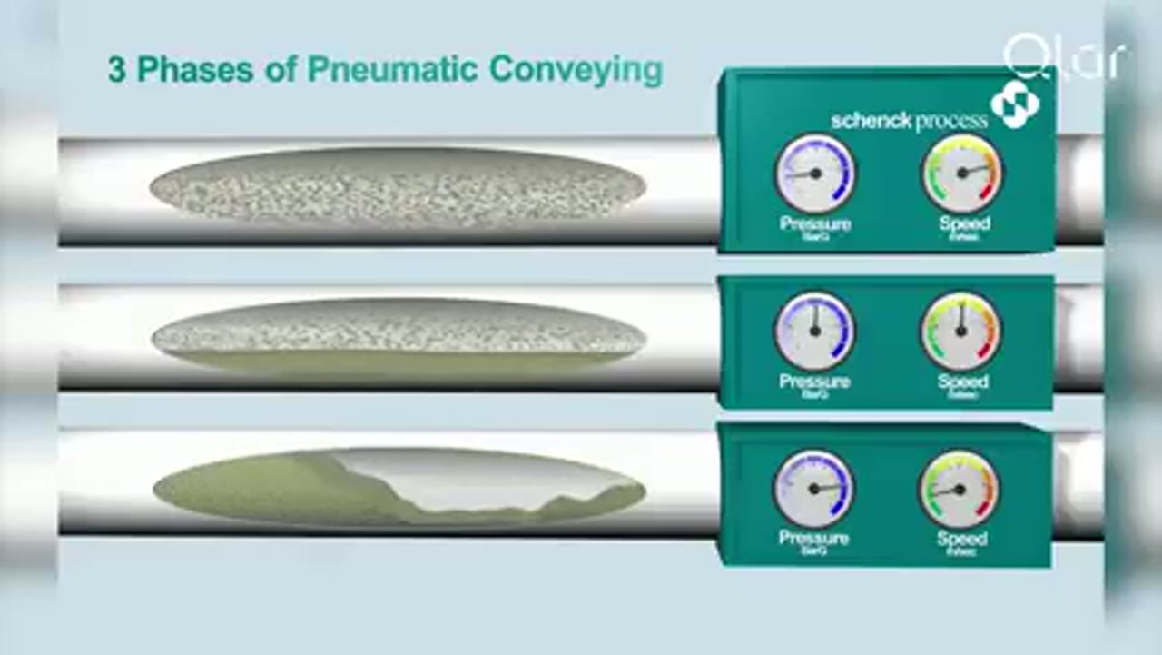

Qlar
Pneumatic Conveying Explained: The 3 Key Phases of Dense Phase Conveying
Qlar explains the three phases of dense phase pneumatic conveying and where each one fits when powders, granules and bulk solids have to move without being damaged.
Powder Process-Solutions
Pressure Dilute Phase
The Powder Process-Solutions animation shows a positive-pressure dilute-phase arrangement in which a gas stream pushes suspended material through the conveying line toward the receiver.
Total reach: 92,214
Supplier discovery
Companies demonstrating Pneumatic Conveying
Frequently asked questions
Which interfaces belong inside the pneumatic conveying system boundary
Include material pickup, solids feed, pipeline, bends, receiver, filtration, gas mover, discharge device, controls, and the readiness signals exchanged with source and destination equipment.
What should a system trial prove before final design
A representative trial should establish stable transfer, pressure behavior, product condition, filter loading, discharge reliability, and restart after an interruption across the required operating range.
How are pressure, vacuum, dense phase and dilute phase related
Pressure and vacuum describe how the gas-pressure difference is created. Dense and dilute phase describe material concentration and conveying behavior, so a pressure or vacuum arrangement still needs its own phase assessment.
Related content
Continue exploring
Move from this page to the companies, videos and technical topics that add useful context.