
Application
Pneumatic Conveying in Pharmaceutical Production
Answer in brief
In pharmaceutical production pneumatic transfer means vacuum transfer, for one reason: a vacuum line leaks inward.
A failed seal draws air in rather than releasing product, which is the opposite of what a pressure line does. The exposure then concentrates at the receiver, not along the pipe.
- Use vacuum where the compound is potent.
- Design the receiver filter and discharge as containment components.
- Keep the contact surface a smooth tube, which is its main advantage.
Reviewed October 21, 2026
The problem
A pressure conveying line releases product wherever it leaks, and for a potent compound that is unacceptable along the whole length of the route. A vacuum line fails the other way: a leak admits air, the product stays inside, and the containment is intrinsic rather than maintained.
That shifts the problem to the ends. The vacuum receiver has a filter that has to be cleaned of product, and a discharge valve that opens into the next vessel. Those two components are where an operator can meet the compound, and they are where the containment design belongs.
Filter cleaning is the specific issue. A reverse pulse or a mechanical shaker releases the collected product back into the receiver, and the mechanism, its seals and its air supply are all inside the containment boundary. A filter changed by hand on a potent compound is an exposure event unless it was designed not to be.
And everything has to be cleanable and qualified. The advantage of a vacuum line is that its product contact surface is a smooth tube; that advantage is lost if the receiver internals cannot be reached.
In pharmaceutical production the direction of a leak decides the concept, and no other industry asks that question first.
Desired outcome
Transfer by vacuum wherever the compound is potent, so the line itself is intrinsically contained and the design attention goes where the exposure actually is.
A receiver whose filter cleaning mechanism and discharge valve are specified as containment components, with stated performance and a cleaning route that reaches everything.
A documented package: materials, surface finish, containment figures, cleaning method and swab points, under change control.
In a building materials plant the same route is decided by abrasiveness over distance, and dilute phase chosen for a long cement line wears its bends out first.
Process approach
The route is designed as vacuum from the start. A receiver above the destination vessel, a smooth tube from the source, and a discharge valve that opens into a closed connection. The product contact surface is then a tube and a vessel, which is as little as a transfer can be.
The filter is then the design focus. A filter element that can be cleaned in place by a mechanism whose seals are part of the containment, with a defined procedure for element replacement that does not expose the technician. Where the compound is potent enough, element changes happen inside a containment enclosure.
The discharge valve is treated the same way: for a potent compound a split butterfly arrangement keeps the contaminated faces together, and its containment performance is a measured figure for that size.
Cleaning is designed next, in place or out of place, with spray coverage or a dismantling route, and swab points defined. And the vacuum source itself is specified with its exhaust filtration, since that is the one place air leaves the system.
- Vacuum rather than pressure wherever the compound is potent, for intrinsic containment.
- Receiver filter cleaning mechanism specified as a containment component.
- Element replacement procedure designed not to expose the technician.
- Discharge valve with measured containment performance for the installed size.
- Cleaning route defined, in place or out of place, with swab points.
- Vacuum source exhaust filtration specified, since that is where air leaves the system.
Selection factors
- Containment band of the compound, which is the reason vacuum is chosen.
- Receiver filter cleaning method and whether element changes can be contained.
- Discharge valve type and its measured containment performance.
- Cleaning strategy, in place or out of place, including whether every surface is reachable.
- Product fragility, since vacuum transfer still has a velocity.
- Exhaust filtration on the vacuum source.
Common failure modes
- Pressure conveying used for a potent compound, so every seal is a potential release point
- Receiver filter element changed by hand with no containment arrangement
- Filter cleaning mechanism seals left out of the containment boundary
- Discharge valve containment taken from a figure measured on a different size
- Cleaning route that cannot reach the receiver internals, found during swab recovery
- Vacuum source exhaust unfiltered, so the one air exit is uncontrolled
Partner with powderbulkvideos.com
Put a relevant technical solution in this decision path.
Connect your company and video evidence with clearly labelled visibility where engineers evaluate this material, application, industry or product.
Frequently asked questions
Why vacuum rather than pressure?
Because the failure direction is inward. A leak in a vacuum line admits air instead of releasing product, which makes the containment intrinsic along the whole route.
Where is the exposure then?
At the receiver: the filter that collects product and the valve that discharges it. Those are the components that need stated containment performance and a procedure for element changes.
Is the product contact surface really simpler?
Yes, and that is the quiet advantage. A smooth tube and a vessel is far less to clean and validate than a mechanical conveyor's flights, bearings and seals.
Related content
Continue exploring
Move from this page to the companies, videos and technical topics that add useful context.
Companies

Videos

VAC-U-MAX
VAC-U-MAX: Signature Series Packaged Vacuum Conveying Systems
With over 65 years of experience in pneumatic conveying and more than 10,000 powders and granular materials handled, VAC-U-MAX packages its Signature Series vacuum conveying systems as complete units: receiver, UL-listed controls, convey hose, filters, and vacuum producer.
Total reach: 10,831

VAC-U-MAX
VAC-U-MAX: Vacuum Receiver Designs, Features, Benefits and Filter Types
This VAC-U-MAX video explains vacuum receiver configurations and the roles of filtration, discharge, and cleaning. It helps define the system boundary and major components. Capacity, filtration, pressure loss, discharge, and combustible dust suitability depend on the material and the complete installation.
Total reach: 18,143
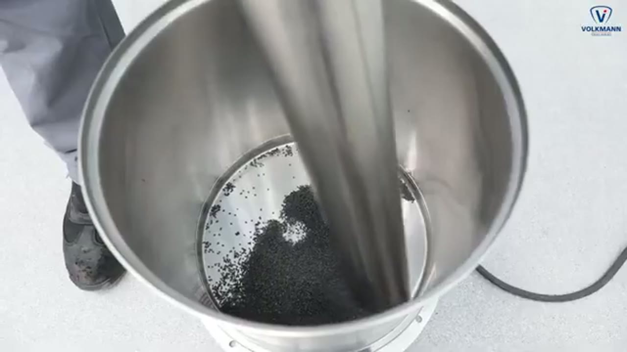
Volkmann GmbH
Suction lance for powder feeding
The Volkmann video shows powder being introduced from a drum or container through a suction lance into a vacuum conveying line. It shows the pickup boundary and the need to admit material and conveying air in a controlled way. Capacity and suitability depend on the powder and need a conveying trial with the actual material.
Total reach: 1,938