
Comparison
Rotary Valve vs Screw Feeder for Bulk Solids
Answer in brief
Choose a rotary valve when continuous pocket discharge must also limit gas leakage across a pressure boundary. Choose a screw feeder when controlled extraction from an elongated hopper outlet, wider turndown, or positive solids transport is the governing duty. Neither device is a universal explosion-isolation barrier.
By Editorial Team · Published July 15, 2026 · Updated July 26, 2026

Sponsored visibility
Featured videos for this topic
Paid placements are clearly marked and remain separate from the editorial related-video selection.
Start by separating four different duties
A feeder may withdraw material from a hopper, meter solids, transport them a short distance or maintain a gas-pressure boundary.
Rotary valves and screw feeders overlap on the first two duties. They behave very differently on the last two.
How a rotary valve works
A rotating pocketed rotor accepts material at the inlet and releases it at the outlet.
The housing, end plates and rotor clearances restrict gas flow but do not create a perfectly tight seal.
Peer-reviewed experiments show that leakage depends on pressure differential, speed, clearance and valve geometry. Leakage gas can oppose solids entering the pockets and reduce effective capacity.
Engineering visual guide
How the system behaves
These conceptual diagrams connect the operating principle, equipment internals and engineering review points. They are explanatory and not fabrication drawings or a substitute for project-specific calculations.
Engineering infographic
Side-by-side operating principles
Conceptual side-by-side operating schematic for Rotary Valves; use it to structure an engineering review, not as a fabrication drawing or project-specific design.
How a screw feeder works
A rotating helical flight extracts material along an inlet and moves it axially toward discharge.
Mass-flow screw designs vary pitch or shaft diameter so withdrawal capacity increases along a slotted hopper outlet.
A standard screw feeder is not a gas-tight airlock. A compacted plug or specialized pressure feeder is a different engineered system and should not be assumed from the word “screw”.
Decision matrix
| Decision | Rotary valve | Screw feeder |
|---|---|---|
| Pressure differential | Can restrict leakage when clearances and rating suit the duty | Normally requires another pressure-sealing arrangement |
| Hopper extraction | Needs a suitable inlet transition and venting of leakage gas | Can extract progressively across a long slot when geometry is designed for mass flow |
| Metering | Pocket displacement gives an approximate volumetric basis; filling efficiency varies | Volumetric delivery depends on fill, pitch, speed and material state |
| Particle stress | Particles can be trapped at rotor tips and sheared | Particles experience flight, trough and compaction shear |
| Wear response | Clearance growth increases leakage and can reduce filling | Flight and trough wear change capacity and backflow |
| Cleaning | Pockets, tips, end clearances and seals are critical | Flights, shaft, trough, end bearings and discharge are critical |
Engineering infographic
Selection envelope
Conceptual selection envelope for Rotary Valves; use it to structure an engineering review, not as a fabrication drawing or project-specific design.
Material behavior changes both devices
Cohesive powder can bridge above either inlet. Floodable fine powder can flush through clearances or continue flowing after speed is reduced.
Large, fibrous or fragile particles may jam or shear in a rotary valve. The same particles may wrap, compact or break in a screw.
Representative tests should include the material’s credible moisture, consolidation time, temperature and foreign-particle condition.
Partner with powderbulkvideos.com
Put your expertise beside the decisions engineers are making.
Connect a relevant company profile and technical video portfolio with clearly labelled visibility on this topic.
Pressure sealing is where the choice often becomes clear
A rotary valve can feed a pneumatic line or discharge a receiver while limiting gas flow between pressure zones.
It still needs a leakage-gas balance, pressure rating and clearance plan — the rotary valve selection and sizing guide works through those steps. The vent hopper above the valve must let leakage gas escape without fluidizing or blocking incoming powder.
A screw feeder is usually stronger when the duty requires extraction from a long outlet or controlled transport into the next machine without a significant gas differential.
Unsuitable scenarios
A rotary valve is a weak choice when particles cannot pass the inlet shear zone, abrasive wear would quickly destroy the leakage limit, or cleaning access cannot reach pockets and end clearances.
A screw feeder is a weak choice when the device is expected to serve as an unverified airlock, when product compaction is unacceptable, or when the hopper interface cannot provide uniform withdrawal.
Explosion isolation remains a separate decision
OSHA’s combustible-dust guidance describes specialized close-clearance rorotary valvesr monitored material-choke arrangements as possible isolation devices only when designed, installed and maintained for that validated function.
A normal process rotary valve does not become explosion isolation because it has several vanes. A normal screw feeder does not become isolation because it contains material.
Engineering infographic
Failure and safety comparison
Conceptual failure and safety comparison for Rotary Valves; use it to structure an engineering review, not as a fabrication drawing or project-specific design.
Acceptance tests
- Measure minimum, normal and maximum solids rate with representative material.
- Verify the hopper flow pattern across the full outlet.
- For rotary valves, measure leakage gas and filling performance at operating differential pressure.
- For screws, measure torque, fill, discharge pulsation and residual material across the speed range.
- Inspect product damage, wear points, seals and cleaning access.
- Test jam, overload, loss of speed feedback and safe restart.
Frequently asked questions
Which option provides an airlock?
A rotary airlock is designed to restrict airflow while transferring solids, although it is not a perfect gas seal. A conventional screw feeder does not inherently perform the same function.
Which option gives better feeding accuracy?
Accuracy depends on the material, mechanical design, inlet conditions, operating range, and controls; neither technology is automatically more accurate in every application.
Can both technologies handle abrasive powder?
Application-specific versions may do so, but speed, materials, wear surfaces, clearances, and maintenance strategy must be evaluated for the actual powder.
Related content
Continue exploring
Move from this page to the companies, videos and technical topics that add useful context.
Companies
Videos
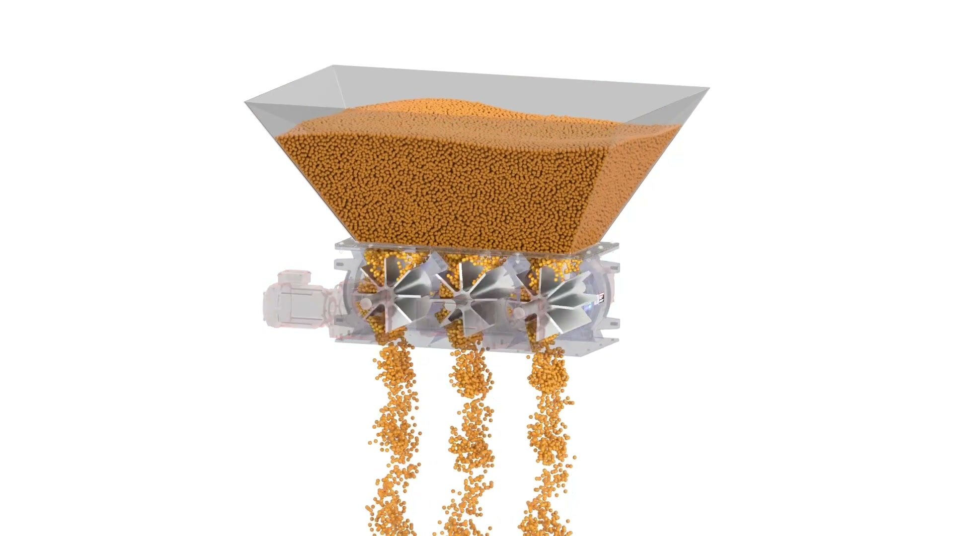
ACS Valves
ACS Multi-Port Rotary Valve in 3D
ACS Valves uses a 3D animation to explain a multi-compartment rotary-airlock arrangement for high-volume discharge duties with independent rotors and drives.
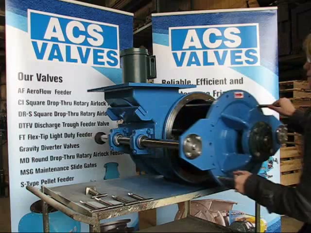
ACS Valves
ACS Quick Clean Rotary Valve Demonstration
In this 65-second ACS Valves clip, a presenter opens a Quick-Clean rotary valve without tools: handles release, the rotor and endplate slide out on RotorRail supports, and a locating key guides reassembly. What the demo establishes is physical access to the product-contact zone — cleaning validation and sanitary certification still depend on the supplied model and the site's procedure.

Airlock
Airlock: Dairy Standard Rotary Valves
Airlock video on the DCSR Version 2.0 rotary valve range (2T and 2TE): drop-through and blow-through configurations for feeding, metering, and pneumatic conveying, with a detachable rotor and end cover for cleaning access in dairy service.
Total reach: 20,550
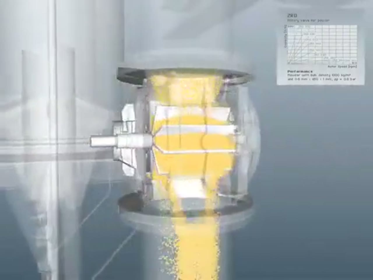
Coperion
Coperion ZRD Rotary Valve for Powder Applications
Coperion presents the ZRD rotary valve and the design choices that adapt it to powder discharge, metering and pneumatic-conveying service.
Total reach: 10,327
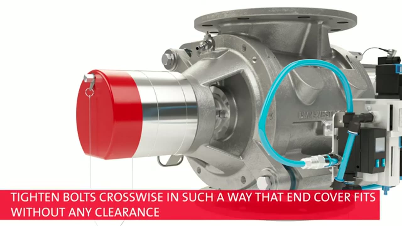
DMN-WESTINGHOUSE
DMN-WESTINGHOUSE MZC-II Basic Inspection and Cleaning
DMN-WESTINGHOUSE demonstrates the basic inspection and cleaning context for an MZC-II rotary valve and states the safety boundary for maintenance work.
Total reach: 2,149

Prater Industries
How To Select The Proper Rotary Airlock Valve
Prater Industries explains the process information engineers need before choosing and sizing a rotary airlock valve.
Total reach: 3,601

Kice Industries
Kice VJX Airlock Installation
Kice Industries demonstrates installation considerations for its VJX airlock at a dry-bulk process interface.

KREISEL Industries GmbH
Kreisel: Screw Pump vs. Rotary Valve
This video presents KREISEL rotary valves and the process duties that distinguish a rotary valve from alternative feeding equipment.
Total reach: 6,223