
Technology guide
Rotary Valves
Answer in brief
A rotary valve meters powder or granules through the pockets of a rotating rotor while restricting gas flow between zones at different pressures. It is never fully gas tight, because the clearances that let the rotor turn also leak air.
Selection weighs capacity, leakage, pocket filling, shear, wear and pressure rating together, especially when the valve feeds a positive-pressure conveying line.
By Editorial Team · Reviewed July 13, 2026 · Updated July 26, 2026

Sponsored visibility
Featured Rotary Valves videos
Paid placements are clearly marked and remain separate from the editorial related-video selection.
Material enters rotor pockets at the inlet, travels with the rotor and leaves at the outlet. The clearances needed for rotation also create leakage paths. Product behavior and differential pressure determine whether pockets fill and discharge consistently.
Function in the process
Rotary valves are often described as feeders, airlocks and discharge devices as though the terms were interchangeable. They are not. Below a dust collector, the valve discharges solids while maintaining suction.
At a pressure conveying inlet, it introduces solids against conveying pressure and must limit reverse gas flow. As a volumetric feeder, its speed influences delivered volume, but actual mass rate depends on pocket filling and bulk density. A specification should name the principal duty and state every secondary duty explicitly.
Gas leaking back through the inlet can aerate fine powder, reduce the effective bulk density in each pocket and oppose gravity flow. Leakage gas belongs in the conveying-air and filter balance, and it needs a credible path away from the inlet; simply increasing rotor speed can make filling worse while adding shear and wear.
Fine powder, high differential pressure and worn clearances raise the stakes, and hard particles can become trapped between rotor and housing. AIChE guidance on handling rotary airlock leakage examines this interaction in pneumatic conveying systems.
Material behavior comes first
Bulk solids do not behave like liquids. Cohesion, wall friction, compressibility, permeability, particle shape, moisture and storage time influence whether material reaches the valve and how it passes through. Research on food powders shows that particle size and bulk density alone cannot reliably predict flow or wall friction, so representative flow testing matters wherever failure has serious consequences.
Engineering infographic
Operating sequence
Conceptual operating sequence for Rotary Valves; use it to structure an engineering review, not as a fabrication drawing or project-specific design.
Engineering inputs
- Required solids rate and pocket filling factor.
- Particle size, hardness and shear sensitivity.
- Differential pressure and gas leakage limit.
- Temperature and thermal expansion.
- Rotor tip clearance and wear allowance.
- Venting, cleaning and explosion isolation duty.
The upstream bin, outlet and downstream equipment must be designed together with the valve, a point long made in AIME's guidance on selecting and sizing feeders, bins and stockpiles. A feeder cannot correct a hopper that forms a stable arch. A shutoff gate cannot meter flow reliably. And a pressure boundary cannot be assumed from the equipment name.
Capacity and control
Geometric displacement gives a theoretical volume per revolution. Real delivery depends on usable pocket volume, fill efficiency, material bulk density and how completely each pocket empties, and all of these shift with level above the valve, gas leakage, speed, cohesion and aeration. The design basis should state minimum, normal and maximum mass rate together with the bulk-density range and the intended speed range.
Check the interfaces at both ends. The hopper outlet must feed the full inlet area without forming a stable arch or rathole, and the discharge must give material and displaced gas enough room to leave the pockets. A restrictive adapter or a poorly vented blow-through arrangement can make an adequately sized valve appear too small.
Rotor speed alone does not guarantee mass flow. A stable speed with declining throughput can indicate poor filling, leakage or buildup. Controls should therefore distinguish commanded speed from actual process performance: position feedback, motor load, mass flow, weight change and downstream pressure each reveal different failure modes, and the useful signal depends on the duty.
Machine cutaway
Inside a rotary airlock
Conceptual cutaway of a drop-through rotary valve showing product pockets and the rotor-to-housing interface. Geometry, clearances and leakage behavior remain design- and duty-specific.
Clearance, wear and failure modes
Rotor-to-housing clearance is a functional compromise. Smaller clearance reduces leakage but increases sensitivity to thermal growth, distortion, deposits and hard particles. More clearance tolerates contamination yet passes more gas and weakens the separation between pressure zones, an effect documented in published measurements of rotary valve leakage. Cold and hot conditions, material temperature, housing temperature and credible upset temperatures all belong in the review.
Abrasive material changes both capacity and risk over time because wear opens leakage paths. Fragile granules may be trapped at the inlet shear line, while fibrous or sticky solids can smear across end plates and pocket surfaces. Selection should address rotor edge geometry, pocket form, surface finish, replaceable wear parts and the inspection method for the actual failure mechanism.
- Air leakage restricts inlet flow.
- Oversize particles jam the rotor.
- Close clearances damage shear-sensitive product.
- Wear increases leakage and reduces separation.
- Buildup prevents pocket discharge.
Safety and maintenance
The rotor creates severe shear points. Isolation must prevent both rotation and material movement, and stored bulk material can move after a drive stops. Moving rotors, blades and actuators require guarding and energy isolation; OSHA's machinery and conveyor rules give the regulatory context. Pressure, vacuum and combustible dust hazards belong in the safe work method for opening or removing the valve.
A rotary airlock is not automatically an explosion isolation device. If the valve is claimed as part of an explosion-isolation concept, verify the exact certified configuration and installation separately; normal airlock performance does not establish an explosion-protection function.
Selection, commissioning and acceptance
- Define the material range and process duty.
- Confirm bin flow and outlet geometry.
- Set capacity, pressure and leakage requirements.
- Review wear, cleaning and contamination risks.
- Select instrumentation and failure response.
- Test the complete interface under representative conditions.
- Document maintenance limits and spare parts.
Commission first without material to confirm rotation, direction, guarding, position feedback and abnormal noise. Then introduce material at a controlled rate and record throughput, valve speed, drive load, upstream behavior, leakage indication and downstream pressure. Repeat the checks at the important duty points rather than accepting one favorable run.
Establish a clean baseline for rotor contact, leakage, wear, torque, temperature, noise and cycle time. A trend away from that baseline can identify deterioration before capacity is lost or a seal fails. Define who may respond to a jam, how pressure and stored material are isolated, and which clearances or wear observations trigger repair.
Engineering infographic
Functional zones and interfaces
Conceptual functional zone schematic for Rotary Valves; use it to structure an engineering review, not as a fabrication drawing or project-specific design.
How to select Rotary Valves
Start with the material and duty
Document the bulk density, particle-size range, flow behavior, abrasiveness, temperature, moisture sensitivity, and any tendency to smear, compact, bridge, or degrade. Then define required throughput, operating speed, pressure differential, leakage tolerance, inlet conditions, and the equipment immediately upstream and downstream.
Review design and maintenance constraints
Compare rotor geometry, pocket volume, clearances, construction materials, seals, bearings, drive arrangement, access for inspection, cleaning method, and replaceable wear components. Where hygiene, hazardous-area, or combustible-dust requirements apply, request documented evidence for the exact valve configuration rather than relying on a general product-family claim.
Final sizing and suitability should be confirmed with the equipment manufacturer or a qualified bulk-solids engineer using representative material data and the real operating envelope.
Partner with powderbulkvideos.com
Place your video in the engineering context buyers are researching.
Use a relevant company profile and technical video to demonstrate this technology before engineers reach the supplier shortlist.
Engineering infographic
Engineering review envelope
Conceptual engineering review envelope for Rotary Valves; use it to structure an engineering review, not as a fabrication drawing or project-specific design.
Continue your research
Rotary Valves guides and answers
Popular on powderbulkvideos.com
Popular Rotary Valves videos

Airlock
Airlock: Dairy Standard Rotary Valves
Airlock video on the DCSR Version 2.0 rotary valve range (2T and 2TE): drop-through and blow-through configurations for feeding, metering, and pneumatic conveying, with a detachable rotor and end cover for cleaning access in dairy service.
Total reach: 20,549
Coperion
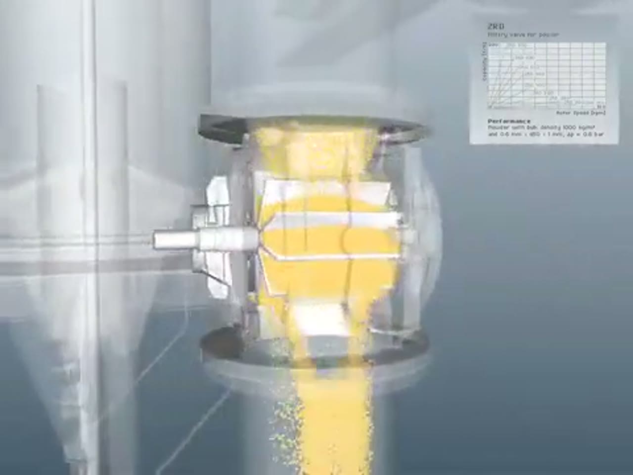
Coperion ZRD Rotary Valve for Powder Applications
Coperion presents the ZRD rotary valve and the design choices that adapt it to powder discharge, metering and pneumatic-conveying service.
Total reach: 10,326

KREISEL Industries GmbH
Kreisel: Screw Pump vs. Rotary Valve
This video presents KREISEL rotary valves and the process duties that distinguish a rotary valve from alternative feeding equipment.
Total reach: 6,222

Prater Industries
How To Select The Proper Rotary Airlock Valve
Prater Industries explains the process information engineers need before choosing and sizing a rotary airlock valve.
Total reach: 3,601
DMN-WESTINGHOUSE
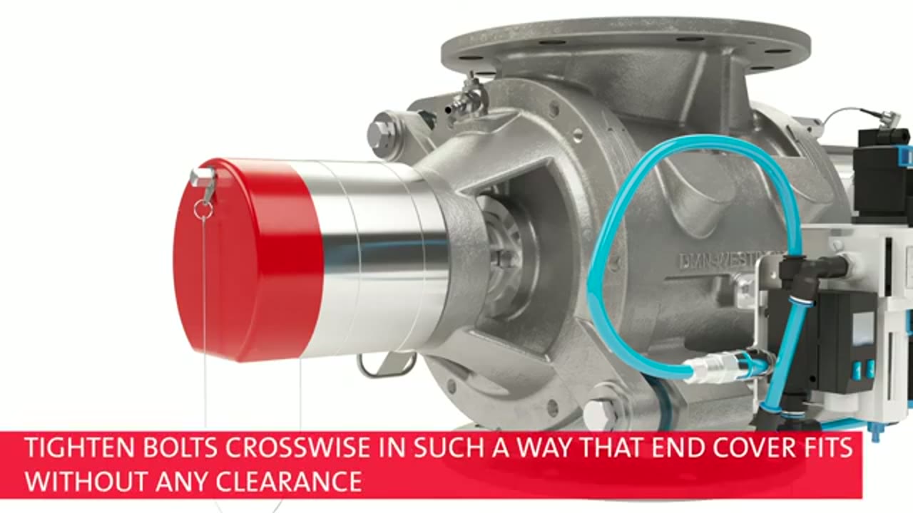
DMN-WESTINGHOUSE MZC-II Basic Inspection and Cleaning
DMN-WESTINGHOUSE demonstrates the basic inspection and cleaning context for an MZC-II rotary valve and states the safety boundary for maintenance work.
Total reach: 2,149

Kice Industries
Kice VJX Airlock Installation
Kice Industries demonstrates installation considerations for its VJX airlock at a dry-bulk process interface.
Supplier discovery
Companies demonstrating Rotary Valves
Frequently asked questions
How does a rotary airlock valve work?
A pocketed rotor turns inside a close-fitting housing, accepting bulk material at the inlet and discharging it at the outlet while restricting uncontrolled airflow between the two sides.
Is a rotary valve the same as a rotary feeder?
The terms overlap, but the required function matters. A rotary valve may provide an airlock, controlled discharge, or volumetric feeding; it is not automatically a precision feeder.
What information is needed to select a rotary valve?
Selection starts with material properties, throughput, pressure differential, temperature, leakage tolerance, upstream and downstream equipment, cleaning needs, and the applicable safety requirements.
Can a rotary valve handle abrasive powder?
Some designs can be configured for abrasive duty, but materials, clearances, speed, coatings, and replaceable wear parts must be evaluated for the actual powder and service conditions.
Why does a rotary valve leak air?
Some clearance is required for rotation, so leakage cannot always be eliminated. Pressure differential, clearances, wear, rotor design, speed, and product in the pockets all influence leakage.
Related content
Continue exploring
Move from this page to the companies, videos and technical topics that add useful context.