
Application
Explosion Isolation in Energy & Power
Answer in brief
In fuel handling the ducts are long and the fuel changes.
A silo, a mill and a collector are joined by conveying runs measured in tens of metres, and the material moving through them is whatever was delivered this month. Isolation has to hold for the whole fuel envelope, not for the design fuel.
- Set the isolation case on the worst credible fuel, not the specified one.
- Treat smouldering nests as the ignition source they usually are.
- Keep devices workable outdoors and in winter.
Reviewed October 21, 2026
The problem
Fuel handling is the one place where the connecting duct is the plant. A reclaim conveyor, a mill feed, a classifier return and a filter extraction add up to long runs between vessels, and a deflagration that starts anywhere in that chain has somewhere to go.
The fuel makes it worse. A plant commissioned on bituminous coal now takes wood pellets, sunflower husk, olive residue or torrefied material, often blended and rarely identical between deliveries. Each of those has its own Kst value, its own minimum ignition energy and its own dust fraction, and the isolation installed for the original fuel was certified against one set of numbers.
The ignition source is also different from most industries. Biomass self heats. A smouldering nest in a silo or a hot particle leaving the mill is not a rare abnormal event; it is the normal failure mode, and it feeds the duct directly.
A power or biomass plant changes its fuel more often than its equipment, and isolation certified once rarely covers what arrives later.
Desired outcome
Every connection between protected vessels carries a tested isolation device within its certified range, assessed against the full fuel envelope the plant actually receives.
Detection that is appropriate to smouldering rather than only to flame, so the event is caught while it is still a hot nest and not after it has become a deflagration.
Devices that still work in February: outdoors, wet, cold, with the dust that fuel handling generates sitting on everything.
In a building materials plant the trap is the opposite assumption: the main product is inert, so the whole plant is treated as inert and the one combustible additive is missed.
Process approach
The first piece of work is the fuel envelope. Not the design fuel, but the range of materials the plant is contractually and practically able to receive, with explosion characteristics measured on samples that include the fines.
Isolation is then placed where the chain can be broken into sections rather than everywhere. Long conveying runs are the awkward case: flap valves depend on flow direction and need a distance window, and a run that is too long for one device and too short for two is a layout problem rather than a device problem.
Detection is chosen for the ignition source that is actually present. Carbon monoxide monitoring in silos finds a smouldering nest hours before anything optical would, and that time is what lets the plant act with a fuel transfer rather than with a suppression system.
Then the device has to survive the environment. Fuel handling is outdoors or semi enclosed, the dust is sticky when wet, and a flap valve whose hinge has seized under a layer of damp fuel dust is a closed duct with a certificate on it.
- Fuel envelope defined and measured before devices are selected.
- Isolation placed to section the chain, with long runs treated as a layout question.
- Carbon monoxide monitoring used where smouldering is the credible ignition source.
- Devices specified for outdoor service, damp dust and winter temperatures.
- Inspection intervals set to the fouling rate, not to the certificate minimum.
- Fuel change treated as a change to the explosion protection case.
Selection factors
- Fuel envelope rather than design fuel: the worst credible Kst and the lowest credible ignition energy across everything the plant can receive.
- Duct length and run geometry, which in fuel handling decides between one device, two devices and a redesign.
- Self heating behaviour of the fuel, which sets the detection method as much as the explosion data does.
- Moisture and fouling, because a device that cannot move when dirty is not a device.
- Ambient conditions at the device position, including winter minimum and driving rain.
- Access for inspection on a conveying run that is often elevated and rarely convenient.
Common failure modes
- Isolation certified for the commissioning fuel while the plant has been firing something else for years
- Flap valve installed against the flow direction it was tested in
- Smouldering nest treated as a housekeeping issue rather than as the plant ignition source
- Hinge or seat seized under damp fuel dust, so the device cannot close when called
- Conveying run too long for one device and left with one anyway
- Fuel change made commercially with no review of the explosion protection case
Partner with powderbulkvideos.com
Put a relevant technical solution in this decision path.
Connect your company and video evidence with clearly labelled visibility where engineers evaluate this material, application, industry or product.
Frequently asked questions
Does switching from coal to biomass change the isolation case?
Yes. Kst, minimum ignition energy and the dust fraction all change, and the self heating behaviour changes the most. A device certified for the original fuel is not automatically valid for the new one.
Why monitor carbon monoxide if the hazard is an explosion?
Because in biomass the explosion usually starts as a smouldering nest. Carbon monoxide rises hours before there is anything to see, which is enough time to move fuel out of the silo instead of relying on a device to contain the result.
How do long conveying runs affect device choice?
Each certified device has a distance window from the ignition source. A long run can fall outside it, which means either sectioning the run with more than one device or changing the layout so a device sits where its certificate applies.
Related content
Continue exploring
Move from this page to the companies, videos and technical topics that add useful context.
Companies

Videos

REMBE® GmbH Safety+Control
REMBE®: Explosion Isolation – REMBE® EXKOP®
This REMBE video explains an active explosion isolation system intended to stop propagation through connected ductwork. The shown equipment is part of explosion mitigation, not a substitute for ignition prevention. Selection requires representative dust test data, a hazard assessment and a coordinated venting, suppression and isolation strategy.
Total reach: 23,512
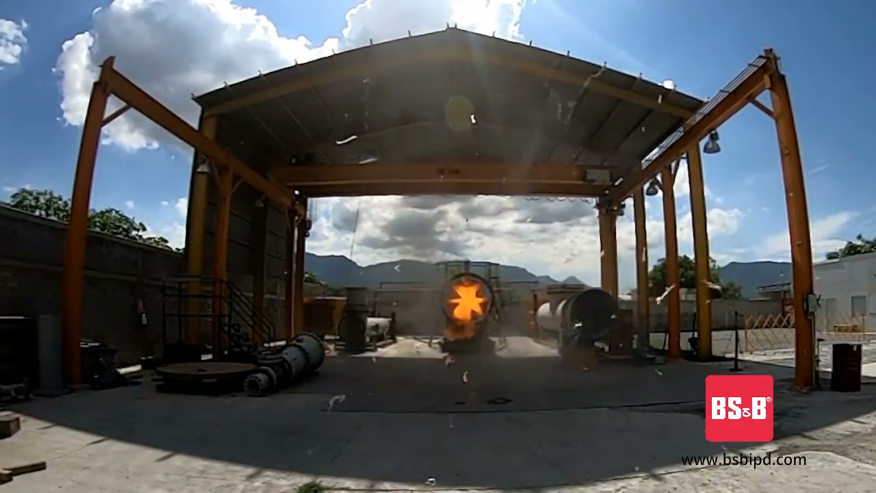
BS&B Safety Systems
BS&B Industrial Explosion Protection Devices
BS&B Safety Systems presents its range of industrial explosion protection devices: explosion vents, flameless venting, and chemical explosion suppression and isolation systems.
Total reach: 2,102

VIGILEX by STIF
VIGILEX by STIF: Explosion Vent Panel and Flameless Devices Protection
The video introduces VIGILEX explosion vent panels and flameless venting devices from STIF. These are mitigation components for limiting pressure effects after a deflagration begins inside protected equipment.
Total reach: 28,590