
Guide
Rotary Valve Selection and Sizing Guide
Answer in brief
Size a rotary valve from required mass flow, not from valve diameter: convert mass flow to volume with a realistic bulk-density range, then match that volume to pocket displacement, speed, and a fill factor based on test or operating data.
Selection also depends on pressure differential, leakage tolerance, temperature, wear, cleanability, and safety constraints. No universal sizing formula covers every bulk solid or system, so final sizing belongs with the manufacturer or a qualified engineer.
By Editorial Team · Published July 15, 2026 · Updated July 26, 2026

Sponsored visibility
Featured videos for this topic
Paid placements are clearly marked and remain separate from the editorial related-video selection.
Define the duty before choosing a valve
A rotary valve can serve three distinct duties: discharging a hopper, limiting air exchange between pressure zones as an airlock, or providing approximate volumetric feeding. One machine can cover more than one duty, but a design proven for one function is not automatically suitable for the others. Decide which duty dominates before comparing models.
Then record the real operating envelope, not a single nominal capacity: minimum, normal, and maximum mass flow, pressure on both flanges, temperature and expected variation, starts and stops, the head of material above the inlet, and the longest expected period with material standing in the rotor. The behavior of upstream and downstream equipment belongs on the same data sheet.
Engineering visual guide
How the system behaves
These conceptual diagrams connect the operating principle, equipment internals and engineering review points. They are explanatory and not fabrication drawings or a substitute for project-specific calculations.
Engineering infographic
System architecture and interfaces
Conceptual system architecture and interface map for Rotary Valves; use it to structure an engineering review, not as a fabrication drawing or project-specific design.
Characterize the bulk solid
Use representative loose and operating bulk density, and document particle size range, flowability, cohesiveness, abrasiveness, friability, moisture sensitivity, and any tendency to smear or compact.
Why it matters: pocket filling can change with inlet geometry, head of material, rotor speed, venting, pressure, and cohesion. Calculate geometric displacement only as an initial reference; it should not be presented as guaranteed process capacity. Request a performance basis that identifies its assumptions and any test material.
Build the sizing calculation around mass balance
Begin with required mass flow, not valve diameter. Convert mass flow to an expected volumetric flow using the credible bulk-density range, then relate that volume to pocket displacement, speed, and a fill factor based on test or operating data.
A single optimistic fill factor hides the effects of aeration, cohesive flow, upstream head, and leakage gas. Record the assumptions so a trial or commissioning result can confirm or replace them.
Check the low-rate case as carefully as the peak. Excessive speed at high demand can reduce filling time and raise product damage; very low speed can make delivery pulsation visible to a downstream continuous process. If the duty requires accurate mass flow, the valve normally needs a measurement and control layer around it. Swept volume by itself is not a gravimetric measurement.
Machine cutaway
Read the rotor-to-housing interface before sizing
Representative drop-through rotary-valve cutaway showing the inlet, pocketed rotor, housing interface and discharge. Pocket fill, clearances, leakage and shaft arrangements remain material-, pressure- and manufacturer-specific.
Specify pressure and leakage as system inputs
A valve feeding a pneumatic conveying line must be assessed with the conveying pressure and air leakage in mind. State the normal and upset pressure on each flange, the gas composition and temperature, and the maximum acceptable leakage into the source vessel.
Leakage depends on clearances, pressure difference, rotor position, material in the gaps, and wear. Treat it as a range in the air balance, not as a fixed catalog number transferred from a different test.
Provide a route for leakage gas where it can interfere with filling. Venting may return gas to a receiver or dust-control system, but that connection must not create an uncontrolled dust path or impose a new restriction. Confirm that the receiver filter and conveying source can accommodate the combined process and leakage flow.
A valve below a filter, cyclone, hopper, or silo also depends on inlet flow and venting. Capacity problems can originate outside the valve, so review the complete interface, not the valve alone.
Review mechanical configuration against the material
Compare open, closed, relieved, or flexible rotor concepts only after defining particle size, hardness, friability, cohesion, and contamination limits. Hard oversize can jam at the shear line. Soft granules can be cut. Sticky product can remain in pockets. Abrasive fines can wear tips and end clearances, changing leakage over time.
Ask how rotor geometry, speed, construction, coatings, and replaceable wear parts address the identified failure mechanism, rather than adding complexity without a testable purpose. Clearances also influence sensitivity to temperature, buildup, and particle trapping; for hot service, review differential thermal expansion before setting an acceptable cold clearance.
Materials of construction, surface treatments, seals, bearings, drive arrangement, and access belong in the same review. Each should match the product and the duty.
Partner with powderbulkvideos.com
Put your expertise beside the decisions engineers are making.
Connect a relevant company profile and technical video portfolio with clearly labelled visibility on this topic.
Separate process isolation from explosion isolation
A normal airlock is not automatically an explosion isolation device. A rotary valve used as an explosion choke needs suitable strength, rigid blades, and controlled clearances. For hazardous-area or combustible-dust duties, ask for certificates and test records covering the exact proposed configuration and applicable duty rather than treating the product family name as certification.
Engineering infographic
Engineering design workflow
Conceptual engineering design workflow for Rotary Valves; use it to structure an engineering review, not as a fabrication drawing or project-specific design.
Verify hygiene, cleaning, and maintenance
Define access, cleaning method, inspection interval, and acceptable product retention. For food or pharmaceutical service, assess product contact materials, seals, retained powder, and the cleaning procedure; FDA guidance expects equipment to be suitable for its use, cleaning, and maintenance.
For hygienic or allergen-sensitive duties, ask how the rotor is withdrawn, which surfaces remain hidden, how heavy parts are handled, and how clean status is verified and documented. Define inspection points before the order, not after the first audit.
Set acceptance criteria before purchase
- Required mass flow across the stated material range.
- Permitted air leakage or pressure effect.
- Product damage, retention, and contamination limits.
- Temperature, wear, and maintenance expectations.
- Cleaning and inspection requirements.
- Safety documentation for the final configuration.
Record the selected rotor, speed, clearances, drive, seals, and construction. Once the duty sheet is complete, compare the scope of supply of shortlisted suppliers in the rotary valve companies Top 10.
Engineering infographic
Verification and acceptance checklist
Conceptual verification and acceptance checklist for Rotary Valves; use it to structure an engineering review, not as a fabrication drawing or project-specific design.
Write a factory and site acceptance plan
A useful factory test checks the offered rotor, drive, clearances, rotation, access, and instrumentation. Representative-material testing is warranted where filling, leakage, degradation, or buildup is uncertain. The site test then verifies the installed interfaces, because hopper flow, venting, conveying pressure, and downstream restriction cannot be reproduced by a no-load shop run.
Record acceptance criteria for sustained mass rate, speed range, drive load, leakage or pressure behavior, product damage, dust release, and clean-down. Include startup, controlled stop, loss of downstream availability, and restart after material has remained in the valve. A signed data sheet should identify which results are measured, which are calculated, and which still require operational confirmation.
Commission with representative material and preserve the tested settings as the operating baseline. Review that baseline after process changes. Final sizing should be confirmed by the manufacturer or a qualified bulk-solids engineer, using testing when material behavior is uncertain.
Frequently asked questions
Which bulk density should be used for sizing?
Use a representative operating bulk density and test sensitivity to realistic variation; the correct value depends on how the material enters and fills the rotor pockets.
Can capacity be calculated from pocket volume alone?
No. Pocket volume is only one input; filling efficiency, speed, bulk density, pressure, inlet conditions, and product behavior all affect delivered capacity.
Who should confirm final rotary valve sizing?
The equipment manufacturer or a qualified bulk-solids engineer should confirm sizing against the actual material, system layout, and operating envelope.
Related content
Continue exploring
Move from this page to the companies, videos and technical topics that add useful context.
Companies
Videos
ACS Valves
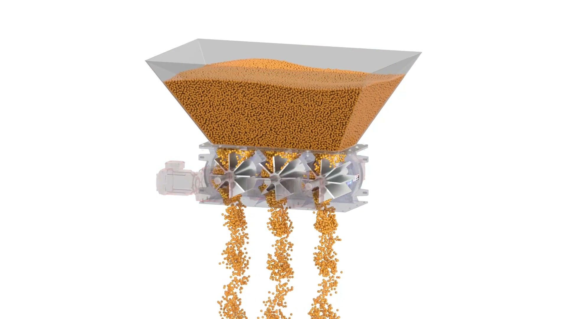
ACS Multi-Port Rotary Valve in 3D
ACS Valves uses a 3D animation to explain a multi-compartment rotary-airlock arrangement for high-volume discharge duties with independent rotors and drives.
ACS Valves
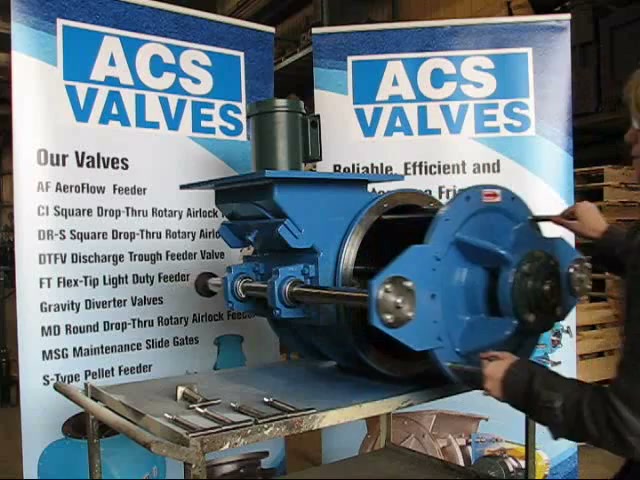
ACS Quick Clean Rotary Valve Demonstration
In this 65-second ACS Valves clip, a presenter opens a Quick-Clean rotary valve without tools: handles release, the rotor and endplate slide out on RotorRail supports, and a locating key guides reassembly. What the demo establishes is physical access to the product-contact zone — cleaning validation and sanitary certification still depend on the supplied model and the site's procedure.

Airlock
Airlock: Dairy Standard Rotary Valves
Airlock video on the DCSR Version 2.0 rotary valve range (2T and 2TE): drop-through and blow-through configurations for feeding, metering, and pneumatic conveying, with a detachable rotor and end cover for cleaning access in dairy service.
Total reach: 20,549
Coperion
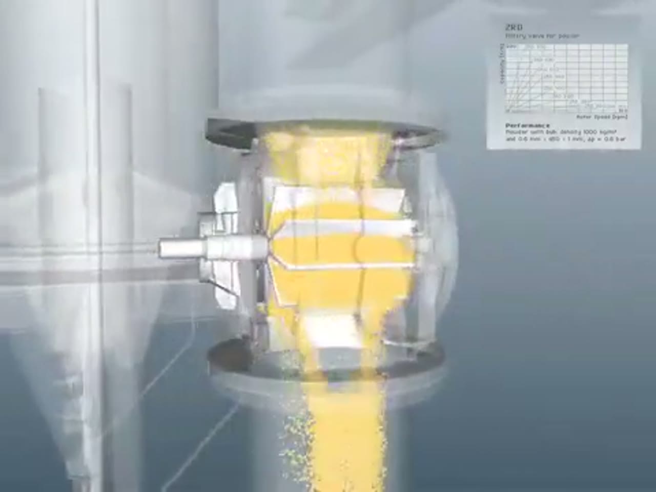
Coperion ZRD Rotary Valve for Powder Applications
Coperion presents the ZRD rotary valve and the design choices that adapt it to powder discharge, metering and pneumatic-conveying service.
Total reach: 10,326
DMN-WESTINGHOUSE
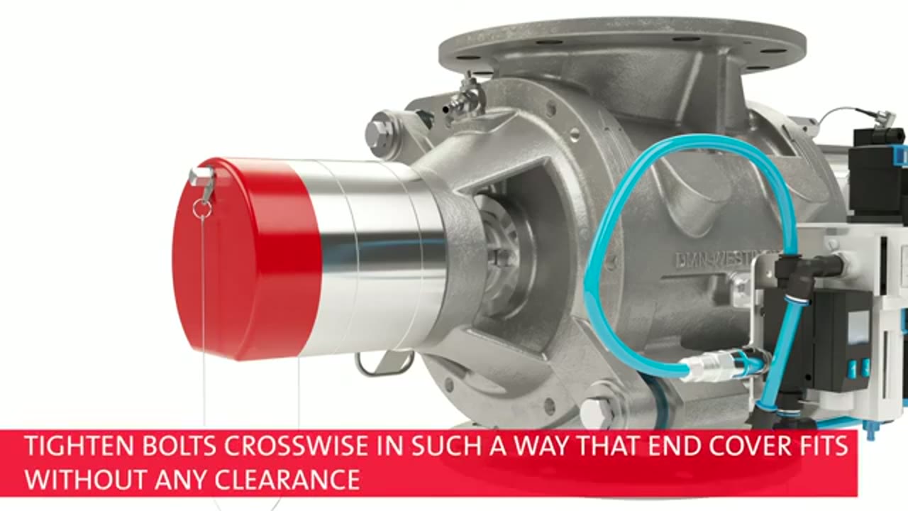
DMN-WESTINGHOUSE MZC-II Basic Inspection and Cleaning
DMN-WESTINGHOUSE demonstrates the basic inspection and cleaning context for an MZC-II rotary valve and states the safety boundary for maintenance work.
Total reach: 2,149

Prater Industries
How To Select The Proper Rotary Airlock Valve
Prater Industries explains the process information engineers need before choosing and sizing a rotary airlock valve.
Total reach: 3,601

Kice Industries
Kice VJX Airlock Installation
Kice Industries demonstrates installation considerations for its VJX airlock at a dry-bulk process interface.

KREISEL Industries GmbH
Kreisel: Screw Pump vs. Rotary Valve
This video presents KREISEL rotary valves and the process duties that distinguish a rotary valve from alternative feeding equipment.
Total reach: 6,222