
Application
Explosion Isolation in Chemicals
Answer in brief
In chemical plants isolation has to work without spoiling the product.
Chemical barriers inject suppressant into the duct, which is effective and often unacceptable for a high purity product, so the geometry has to allow a mechanical device instead.
- Decide early whether suppressant contact is acceptable.
- Design duct geometry to allow a mechanical device if it is not.
- Cover every product, not the easiest one.
Reviewed October 21, 2026
The problem
Chemical plants combine explosible dusts with solvents, inert atmospheres and classified areas, so isolation has to fit into a safety concept that already exists.
The materials also vary between campaigns: a device sized for one dust can be inadequate for the next, and the connections between vessels are often more numerous than in a single-product plant.
Desired outcome
Propagation stopped at every connection, with devices that are compatible with the area classification, the materials and any inerting already in place.
A protection case that survives a campaign change, which means it is written against the most severe material the plant may run rather than the one it is running, and reviewed when a new product is introduced.
Where inerting is part of the basis of safety, devices whose sealing performance is good enough to maintain the atmosphere as well as to stop a flame, with oxygen monitored downstream rather than inferred from the purge flow.
In a food powder plant the deciding document is the connection map, and the gap is almost always the short duct nobody drew.
Process approach
The connection map comes first, as everywhere, and in a chemical plant it includes the nitrogen and vent systems as well as the product lines.
Where inerting is used, isolation serves a different role: it maintains the inert atmosphere as well as stopping flame, and a device that leaks defeats both. Where inerting is not used, the device has to handle the most severe dust on the material list.
Area classification decides what equipment may be installed at all, and the detection method follows from it. Optical detectors and pressure detectors have different requirements and different failure modes in a dusty line.
Material compatibility decides the wetted parts, including the suppressant in a chemical barrier, which must not react with the product it lands in.
The suppressant question is settled first because it determines everything else. A chemical barrier is effective, it works over a wide range of duct geometries, and the agent ends up in the product. If quality cannot accept that, the answer is a mechanical device, and a mechanical device needs a distance window that the duct layout has to provide.
That makes duct geometry a safety decision rather than a piping detail. A metre of straight run added between two vessels can be the difference between a certified option and none at all, and it is far cheaper to add at design than to retrofit into a congested plant.
- Map product, vent and inert systems together.
- Design for the most severe material, not the current one.
- Check suppressant compatibility with every product.
- Suppressant acceptability confirmed with quality before any device is specified.
- Duct geometry designed to provide the distance window a mechanical device needs.
- Protection case written against the most severe material in the campaign plan.
Selection factors
- The material list and its most severe member.
- Area classification, which constrains the device and the detection.
- Inerting, where present, and the sealing performance required to maintain it.
- Suppressant compatibility with every product in the line.
- Campaign changes, and whether the protection remains valid across them.
- Duct geometry available, which decides whether a mechanical device is an option at all.
- Maintenance access under permit, which limits the achievable testing interval.
- Review trigger for a new campaign product, so the case does not quietly expire.
Common failure modes
- Protection designed for the current campaign and left unchanged when the material changes
- Device compatible with the area classification but not with the product it contacts
- Inerting and isolation treated separately, so a leaking device defeats both
- Vent and nitrogen lines left off the connection map
- Detection method chosen without regard to how it behaves in a dusty line
- Chemical barrier specified before quality was asked whether the agent may contact the product
- Duct layout fixed before the isolation concept, leaving no certified option
- Testing interval written to the certificate rather than to what permit conditions allow
Partner with powderbulkvideos.com
Put a relevant technical solution in this decision path.
Connect your company and video evidence with clearly labelled visibility where engineers evaluate this material, application, industry or product.
Frequently asked questions
How does inerting change the isolation requirement?
The device has to maintain the inert atmosphere as well as stop flame. A device that leaks defeats the prevention and the protection at the same time.
What happens when the campaign changes?
The protection may no longer be valid. Devices sized for one dust can be inadequate for a more severe one, so a change of material is a change to the safety case.
Does the suppressant matter chemically?
Yes. It ends up in the product line, so it has to be compatible with everything that passes through, not only with the dust it is meant to quench.
Why does duct geometry decide the method?
Because mechanical devices have a certified distance window from the ignition source. If the duct is shorter than the minimum or longer than the maximum, no mechanical device qualifies, and the layout rather than the device has to change.
Related content
Continue exploring
Move from this page to the companies, videos and technical topics that add useful context.
Companies

Videos

REMBE® GmbH Safety+Control
REMBE®: Explosion Isolation – REMBE® EXKOP®
This REMBE video explains an active explosion isolation system intended to stop propagation through connected ductwork. The shown equipment is part of explosion mitigation, not a substitute for ignition prevention. Selection requires representative dust test data, a hazard assessment and a coordinated venting, suppression and isolation strategy.
Total reach: 23,512
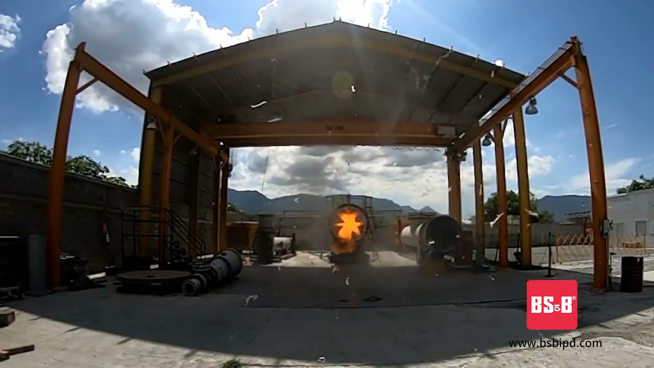
BS&B Safety Systems
BS&B Industrial Explosion Protection Devices
BS&B Safety Systems presents its range of industrial explosion protection devices: explosion vents, flameless venting, and chemical explosion suppression and isolation systems.
Total reach: 2,102

VIGILEX by STIF
VIGILEX by STIF: Explosion Vent Panel and Flameless Devices Protection
The video introduces VIGILEX explosion vent panels and flameless venting devices from STIF. These are mitigation components for limiting pressure effects after a deflagration begins inside protected equipment.
Total reach: 28,590