
Guide
Rotary Airlock Troubleshooting Guide
Answer in brief
Diagnose rotary airlock problems from the symptom and the full process context, not from the valve alone. Leakage, jamming, wear, product damage, and unstable capacity can originate in the valve, the handled material, the pressure conditions, or connected equipment. Isolate safely, record the operating condition first, then match the corrective action to the confirmed cause.
By Editorial Team · Published July 15, 2026 · Updated July 26, 2026

Sponsored visibility
Featured videos for this topic
Paid placements are clearly marked and remain separate from the editorial related-video selection.
Work safely and record the baseline
Stop and isolate the equipment according to the site procedure and the manufacturer's instructions before any inspection. For combustible dust service, do not assume that a stopped valve isolates an event between connected vessels.
Troubleshooting starts with the symptom and the process boundary. Low output, high leakage, noise, heating, and product damage have different causes. Record when the problem occurs, the product and rate being handled, upstream level, downstream pressure, temperature, valve speed, motor load, and any recent process changes. Changing rotor speed before recording this baseline can hide the original fault and create a second problem.
Excessive air leakage
Some leakage is inherent, because a rotary valve needs operating clearance to turn. Check the actual pressure differential, rotor and housing clearances, wear pattern and seal condition, speed, pocket filling, venting, and the connected conveying system.
Leakage often rises as abrasive service changes the rotor and housing. It can also disturb filling above the valve or add air to downstream conveying, so its effects reach beyond the valve itself. Measure against an agreed operating point, since leakage depends on pressure and configuration. Corrective action depends on whether leakage has increased over time or the original valve selection never matched the duty.
Engineering visual guide
How the system behaves
These conceptual diagrams connect the operating principle, equipment internals and engineering review points. They are explanatory and not fabrication drawings or a substitute for project-specific calculations.
Engineering infographic
System architecture and interfaces
Conceptual system architecture and interface map for Rotary Valves; use it to structure an engineering review, not as a fabrication drawing or project-specific design.
Jamming, contact, or high drive load
Look for foreign objects, oversized particles, buildup, product compaction, thermal expansion, damaged components, bearing condition, and misalignment. Do not simply increase drive power without finding the cause, because this may transfer loads to the rotor, shaft, or housing.
Noise or rising temperature calls for the same checks: foreign material, bearings, alignment, deposits, and thermal growth. Do not continue operating a machine with suspected rotor contact. Record where contact marks appear and whether the event follows warmup, cleaning, or a material change.
Rapid wear or product damage
Review material abrasiveness and friability, rotor speed, clearances, construction materials, pressure effects, and the way material enters the valve. Wear protection or a different rotor may help, but reassess the complete operating duty before ordering parts.
Product damage: examine particle size relative to the inlet and clearances, rotor speed, and pocket geometry. Sticky material may smear on contact surfaces and reduce effective pocket volume. Fragile particles may need a different inlet, rotor, or operating speed rather than a larger drive.
Bridging, poor filling, or unstable capacity
A valve cannot deliver stable output when its pockets fill inconsistently. Check whether material actually reaches the inlet: inspect the hopper outlet, inlet geometry, venting, head of material, and product flow behavior. Bridging, poor venting, and upstream compaction can starve the rotor.
Inspect the pockets for buildup, confirm the discharge is clear, and compare actual bulk density with the sizing basis. A stable rotational speed does not guarantee stable mass flow. Cohesive materials may require changes upstream rather than a valve-only adjustment.
Partner with powderbulkvideos.com
Put your expertise beside the decisions engineers are making.
Connect a relevant company profile and technical video portfolio with clearly labelled visibility on this topic.
Use the pressure signature to separate causes
Low capacity is not automatically a small valve. Compare pressure above and below the airlock, conveying-line pressure, upstream level, rotor speed, and drive load over the same period. High reverse leakage with low pocket filling points toward the pressure boundary or wear.
Stable pressure with rising drive load points more toward mechanical contact, trapped material, or deposits. A falling upstream level or intermittent hopper flow moves the investigation above the valve.
Capture the sequence before making an adjustment. Note whether the problem starts after refill, at a particular conveying rate, when the plant warms up, or after a product change. A short trend is usually more useful than one gauge reading taken after the operator has already reduced throughput.
Technical detail view
Locate the symptom inside the machine
Use the generic cutaway to separate the product path, rotor pockets, housing interface and shaft-support boundary before diagnosing leakage, contact or wear. Confirm the actual machine design and isolate energy before inspection.
Recover from a jam without creating a second hazard
A stopped rotor can hold pressure, stored product, and mechanical strain. Isolate all energy sources, prevent material entering from above, and confirm the downstream pressure state before opening access. Reversing or repeatedly jogging the drive can compact an obstruction, damage the gearbox, or release material unexpectedly; use it only when the approved operating procedure and equipment design allow it.
After removal, classify the obstruction. Oversize, metal contamination, fused material, collapsed liner fragments, and product buildup each require different corrective actions. Inspect rotor edges, housing, end plates, seals, and drive components before returning the valve to service. The corrective plan should remove the source of the obstruction, not merely clear the last event.
Diagnose wear from location and mechanism
Uniformly increasing tip and end clearance suggests normal abrasive wear or a material harder than expected. Local scoring can indicate trapped particles, rotor contact, or distortion. Polished inlet edges may show repeated shearing, while deposits in selected pockets may point to moisture, temperature, or poor discharge. Photograph and measure the same locations at each inspection so the rate of change becomes visible.
When leakage rises after repair, confirm rotor orientation, end clearance, seal installation, and the hot operating condition. Replacing only the rotor may not restore the original geometry if the housing or end plates are worn. Compare the repaired baseline with the original commissioning data rather than relying on sound alone.
Engineering infographic
Engineering design workflow
Conceptual engineering design workflow for Rotary Valves; use it to structure an engineering review, not as a fabrication drawing or project-specific design.
Dust leakage and housekeeping
NIOSH treats enclosure and maintained dust controls as engineering measures, and HSE guidance likewise emphasizes sealing leakage points around powder handling equipment. Inspect joints, seals, and the connected extraction. Repair the source rather than relying on cleanup alone.
Engineering infographic
Verification and acceptance checklist
Conceptual verification and acceptance checklist for Rotary Valves; use it to structure an engineering review, not as a fabrication drawing or project-specific design.
Close the investigation with a verification run
Compare measurements with the manufacturer limits, document clearances and wear, and retain samples or photographs where useful. The maintenance record should link the confirmed fault mechanism, the corrective action, and a successful verification run; only then is the investigation complete.
For verification, repeat the operating condition that exposed the fault. Record mass rate, speed, motor load, pressure behavior, leakage indication, temperature, and product condition. Confirm that guards, position feedback, and interlocks were restored and that temporary bypasses were removed.
Update the maintenance trigger if the event revealed an earlier warning sign, such as a rising pressure difference, a longer conveying cycle, increasing motor load, unusual temperature, or a measurable clearance trend. Engage the manufacturer or a qualified engineer when safety functions, pressure containment, combustible dust, structural changes, or a certified configuration are involved, and obtain a competent review before returning the equipment to service.
Frequently asked questions
What commonly increases rotary airlock leakage?
Higher pressure differential, enlarged clearances, wear, rotor speed and design, poor pocket filling, and changes in the connected system can all increase leakage beyond the inherent clearance flow.
Why does a rotary valve keep jamming?
Investigate foreign objects, oversized particles, buildup, thermal growth, damaged parts, bearing condition, alignment, clearances, and unsuitable rotor geometry before increasing drive power.
Can poor capacity come from the hopper?
Yes. Bridging, poor venting, compaction, and inconsistent inlet flow can prevent repeatable pocket filling, so the valve output becomes unstable even at constant speed.
Related content
Continue exploring
Move from this page to the companies, videos and technical topics that add useful context.
Companies
Videos
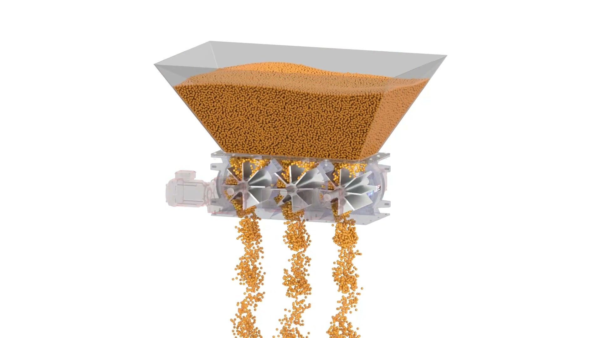
ACS Valves
ACS Multi-Port Rotary Valve in 3D
ACS Valves uses a 3D animation to explain a multi-compartment rotary-airlock arrangement for high-volume discharge duties with independent rotors and drives.
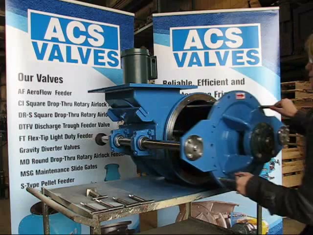
ACS Valves
ACS Quick Clean Rotary Valve Demonstration
In this 65-second ACS Valves clip, a presenter opens a Quick-Clean rotary valve without tools: handles release, the rotor and endplate slide out on RotorRail supports, and a locating key guides reassembly. What the demo establishes is physical access to the product-contact zone — cleaning validation and sanitary certification still depend on the supplied model and the site's procedure.

Airlock
Airlock: Dairy Standard Rotary Valves
Airlock video on the DCSR Version 2.0 rotary valve range (2T and 2TE): drop-through and blow-through configurations for feeding, metering, and pneumatic conveying, with a detachable rotor and end cover for cleaning access in dairy service.
Total reach: 20,549
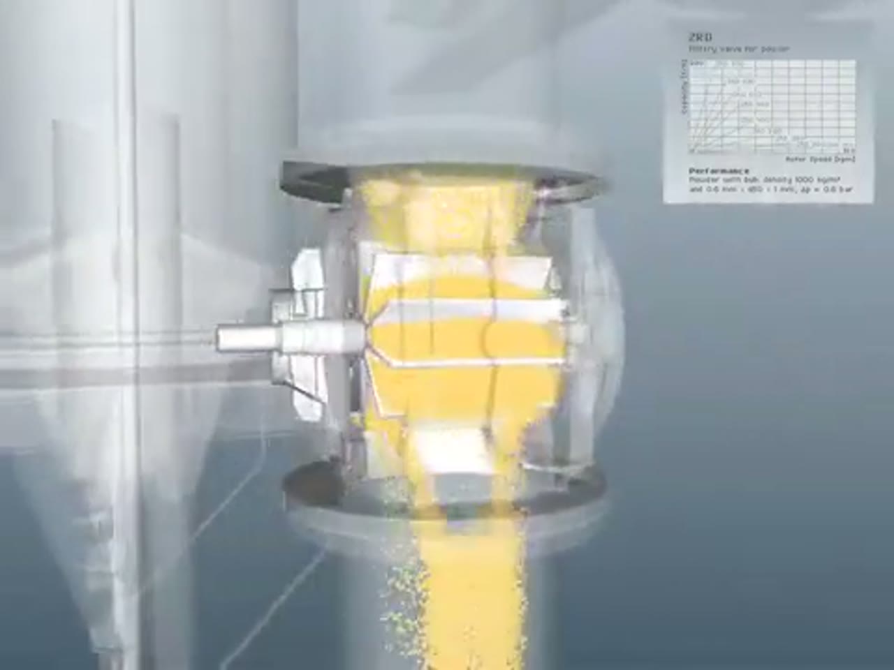
Coperion
Coperion ZRD Rotary Valve for Powder Applications
Coperion presents the ZRD rotary valve and the design choices that adapt it to powder discharge, metering and pneumatic-conveying service.
Total reach: 10,327
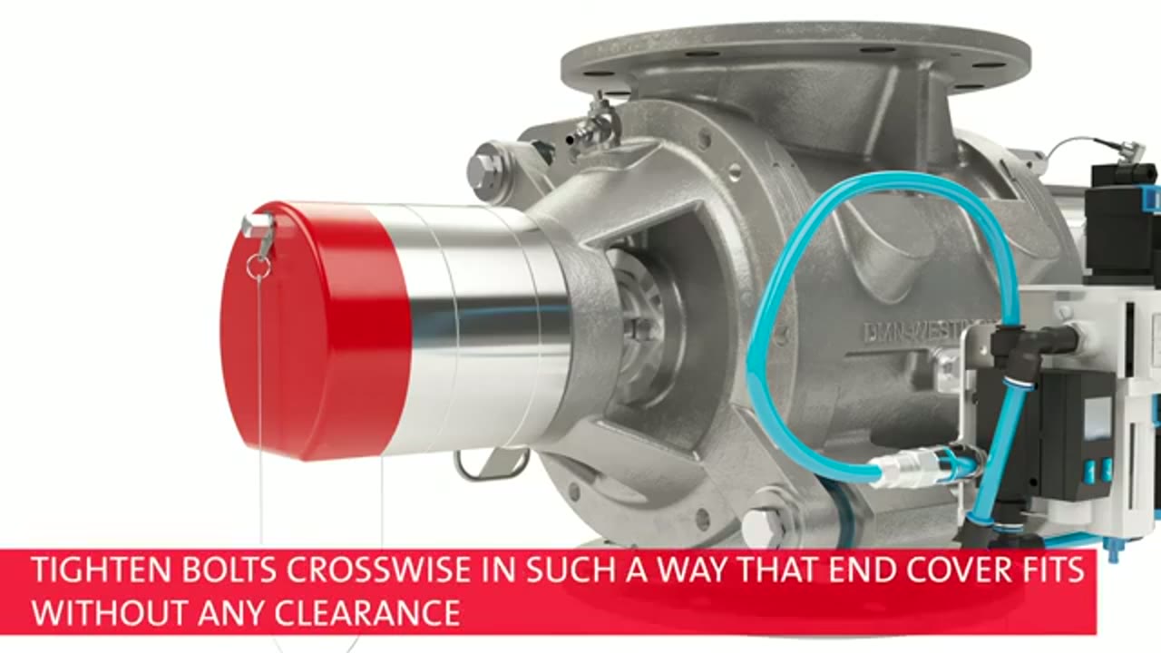
DMN-WESTINGHOUSE
DMN-WESTINGHOUSE MZC-II Basic Inspection and Cleaning
DMN-WESTINGHOUSE demonstrates the basic inspection and cleaning context for an MZC-II rotary valve and states the safety boundary for maintenance work.
Total reach: 2,149

Prater Industries
How To Select The Proper Rotary Airlock Valve
Prater Industries explains the process information engineers need before choosing and sizing a rotary airlock valve.
Total reach: 3,601

Kice Industries
Kice VJX Airlock Installation
Kice Industries demonstrates installation considerations for its VJX airlock at a dry-bulk process interface.

KREISEL Industries GmbH
Kreisel: Screw Pump vs. Rotary Valve
This video presents KREISEL rotary valves and the process duties that distinguish a rotary valve from alternative feeding equipment.
Total reach: 6,222