
Application
Valve and Airlock Selection for Power and Energy Plants
Answer in brief
In fuel and ash handling the valve has to deal with heat and abrasion at the same time.
Fly ash is abrasive and hot, thermal growth closes the clearances a cold fit allowed, and the fuel changes with whatever the plant is burning this season.
- Set clearances for the hot condition, not the cold one.
- Expect fly ash to wear through anything that is not lined.
- Reassess the valve when the fuel changes.
Reviewed October 21, 2026
The problem
Two duties dominate here and they are usually in different parts of the plant. On the fuel side a valve has to pass coal, biomass or a blend, often with tramp material, into or out of a mill circuit that is at an elevated temperature and under some pressure. On the ash side it has to pass fly ash, which is fine, highly abrasive and frequently well above a hundred degrees.
Heat is what breaks the ordinary selection. Rotor and housing grow at different rates, so a valve set to a cold clearance binds as it comes up to temperature; set loose enough to be safe, it leaks, and the leakage figure the conveying system has to live with is the hot one.
Fly ash then removes the material. It polishes, erodes and finds the one unlined surface, and a valve that holds pressure when new is leaking a significant fraction of the conveying air after a season.
Fuel variability closes the loop. A plant that has moved from coal to biomass is passing a different material, with different flow and different explosion characteristics, through valves specified for the original.
A power or energy plant runs its valves hot and schedules its outages far apart, and both facts change the selection.
Desired outcome
A valve that runs through the whole temperature range without binding, with the design leakage taken at operating temperature and carried into the conveying calculation.
Wear confined to replaceable liners and tips with a known service life, so an ash valve is a scheduled consumable rather than a forced outage.
A selection that still holds for the fuels the plant is now permitted to burn, including the blends.
In battery material production the same wear part becomes the problem rather than the solution: a hardened rotor contributes iron against a limit in parts per million.
Process approach
The temperature case is established first, including startup and upset, because that range sets the material pairing and the clearance. Hot service valves are built with the thermal growth calculated rather than assumed, and the cold clearance follows from it.
Wear protection is then designed by location. Fly ash erodes by impingement at some points and by sliding at others, and the right liner is different for each: ceramic tile where particles strike, a harder metal or a compliant rubber where they slide. A single liner specification applied everywhere wears through at whichever point it was wrong for.
On the fuel side the explosion duty is checked. Where the valve is relied on as isolation it carries the certificate, the vane count and the maximum clearance that come with it, and those requirements interact badly with the loose hot clearance the temperature case wants. That conflict is better found at selection than at commissioning.
Finally the fuel envelope is written down, so the next fuel change is a review rather than a surprise.
- Full temperature range established, including startup and upset, before clearances are set.
- Design leakage taken hot and used in the conveying calculation.
- Liner type chosen per location according to impingement or sliding wear.
- Explosion isolation requirements reconciled with the hot clearance.
- Fuel envelope documented so a fuel change triggers a review.
- Wear parts listed as consumables with an interval based on measurement.
Selection factors
- Operating and upset temperature, which sets material pairing and clearance and therefore leakage.
- Abrasiveness and wear mechanism at each position, since impingement and sliding need different liners.
- Fuel envelope, including biomass and blends the plant is permitted to burn.
- Explosion isolation duty in the mill circuit, with its clearance and construction requirements.
- Pressure differential across the valve, which decides how much the worn leakage will cost.
- Access and outage planning, because wear parts are only consumables if they can be reached.
Common failure modes
- Clearance set cold, so the valve binds as it reaches operating temperature
- Cold leakage figure used for the conveying design, with the hot and worn figure much larger
- One liner specification applied to impingement and sliding positions alike
- Explosion isolation certificate requiring a clearance the hot condition cannot hold
- Fuel switched to biomass with no review of the valves in the mill circuit
- Ash valve run to failure because the wear interval was never measured
Partner with powderbulkvideos.com
Put a relevant technical solution in this decision path.
Connect your company and video evidence with clearly labelled visibility where engineers evaluate this material, application, industry or product.
Frequently asked questions
Why does a hot valve need a looser cold clearance?
Because the rotor and housing reach temperature at different rates and grow by different amounts. A clearance that is correct cold closes up as the valve heats, and the result is binding or seizure.
What leakage figure should the conveying system be designed on?
The hot, worn figure. The new cold value is the most optimistic number the valve will ever show, and in fly ash service it stops being representative within a season.
Does a fuel change affect valve selection?
Yes. Flow behaviour, abrasiveness and explosion characteristics all change between coal, biomass and blends, so valves specified for the original fuel need review before the new one is burned.
Related content
Continue exploring
Move from this page to the companies, videos and technical topics that add useful context.
Companies
Videos
Coperion
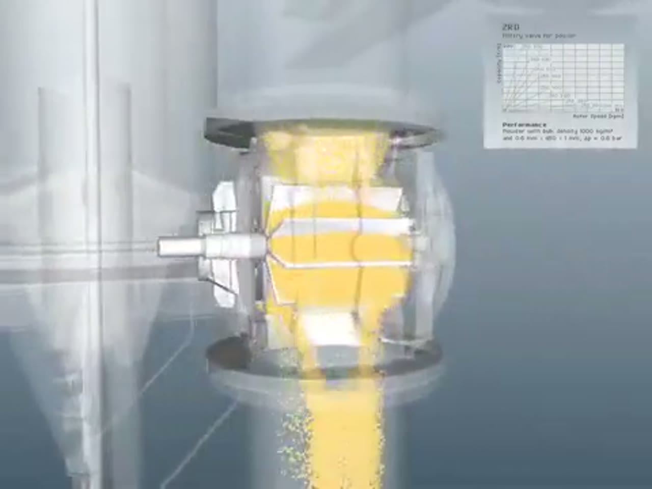
Coperion ZRD Rotary Valve for Powder Applications
Coperion presents the ZRD rotary valve and the design choices that adapt it to powder discharge, metering and pneumatic-conveying service.
Total reach: 10,524

Kice Industries
Kice VJX Airlock Installation
Kice Industries demonstrates installation considerations for its VJX airlock at a dry-bulk process interface.

Vortex – Solids & Bulk Handling Components
Vortex®: Orifice Slide Gate Valve
Vortex's video presents the Orifice Slide Gate Valve: a linear blade carries a machined orifice that moves into or out of alignment with the process connection to isolate or regulate dry-bulk flow.
Total reach: 68,292