
Technology guide
Dense Phase Conveying
Answer in brief
Dense phase pneumatic conveying moves bulk solids at high concentration and low velocity, in modes ranging from fluidized flow to discrete plugs. It is worth investigating for fragile, abrasive or segregation-sensitive products, but only some materials can hold a stable regime. Permeability, air retention, pressure capability and representative conveying trials decide feasibility.
By Editorial Team · Reviewed July 14, 2026 · Updated July 26, 2026

Sponsored visibility
Featured Dense Phase Conveying videos
Paid placements are clearly marked and remain separate from the editorial related-video selection.

Qlar
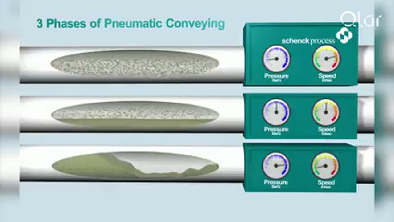
Pneumatic Conveying Explained: The 3 Key Phases of Dense Phase Conveying
Qlar explains the three phases of dense phase pneumatic conveying and where each one fits when powders, granules and bulk solids have to move without being damaged.
This featured spot is open
Show your video here, in front of engineers who are researching this topic.
Dense phase is not one universal flow pattern. It is a family of high concentration conveying regimes that depend strongly on the physical behavior of the bulk solid. Design begins by establishing whether the material can form a repeatable strand, dune, slug, plug, or fluidized flow without unacceptable pressure fluctuation or blockage.
Flow behavior inside the pipe
In dense phase, solids are not uniformly suspended across the pipe. Fine powders with suitable air retention can move in a fluidized dense phase form. Coarser and more permeable materials can form plugs that occupy much of the pipe cross section. Some materials require controlled secondary air to limit plug length or stabilize movement.
The material can transition between regimes when feed rate, gas flow, moisture, or pressure changes. Deposits at the bottom of horizontal pipe do not automatically indicate stable dense phase. Saltation and unstable intermediate flow can produce pressure fluctuation and eventual blockage.
Why material characterization is critical
Particle size and density provide an initial view, but permeability, air retention, deaeration, fine content, cohesion, and particle distribution can determine whether a stable dense mode exists. The Geldart groups are useful for describing fluidization, yet recent classification research shows that borderline powders require more evidence.
Representative pilot conveying is therefore especially valuable. A stable regime is defined by observed flow behavior and a repeatable operating window, not by one solids-loading value. Useful trial evidence is repeatable: pressure traces, gas and solids rates, conveying time, solids loading, plug behavior, product condition, restart performance, and observations from transparent or instrumented sections where available. Repeated large pressure peaks, long stationary plugs, or an inability to restart indicate an unstable duty even when the average velocity looks low.
The difficult material condition belongs in the trial. More fines can increase air retention in one powder and cohesion in another. Moisture can change wall adhesion, permeability, and plug strength. Material that has consolidated during storage may behave differently from a freshly filled sample.
Typical reasons to consider dense phase
- The product is fragile and particle breakage reduces value.
- The solid is abrasive and bend or pipe wear is a major cost.
- A premixed material must arrive with limited segregation.
- The process needs a high solids concentration with less conveying gas.
- The application can support specialized feeding and pressure control.
These are reasons to weigh dense phase against dilute phase, not proof that it is feasible. A cohesive powder can bridge at the feeder. A permeable granular material can form plugs. A material with poor air retention can collapse into an unstable bed. The complete response must be tested or supported by relevant experience.
Pressure vessel and continuous systems
Many dense pressure systems use a vessel that fills at low pressure, closes, pressurizes, conveys, and depressurizes. Vessel size and cycle time influence average capacity. Valve timing, fill level, pressure, and discharge sequence influence each batch.
Continuous dense phase systems use specialized feeding equipment that introduces solids while maintaining the required pressure boundary. The choice between batch and continuous operation depends on capacity, process continuity, material, available height, maintenance, and control requirements.
Engineering infographic
Operating sequence
Conceptual operating sequence for Dense Phase Conveying; use it to structure an engineering review, not as a fabrication drawing or project-specific design.
Pipeline and air injection design
Pipe diameter and route determine the relationship between plug geometry, velocity, and pressure loss. Bends can compact plugs, disturb fluidized flow, or concentrate wear. Long vertical sections and repeated direction changes require careful evaluation.
Some systems add air at selected points to manage plug length or recover pressure. More air is not always better. Excess injection can raise velocity and move the system away from the intended regime. Injection position, flow, timing, and response to pressure should be based on tested behavior.
Controls and operating sequence
Dense phase control often monitors vessel pressure, line pressure, destination availability, valve position, and conveying time. A rising cycle time or changed pressure signature can indicate material variation, filter restriction, buildup, leakage, or wear.
Startup and shutdown need defined sequences. The line may require controlled prepressurization, material admission, conveying, tail clearing, and depressurization. If the line must always be empty before shutdown, that limitation belongs explicitly in the control sequence and operating procedure.
Blockage recovery: available pressure must cover normal transport with margin, but more pressure does not by itself make recovery safe. The design should identify where a plug is likely to form, how it can be located, and whether controlled secondary air, staged depressurization, or mechanical access is provided. Opening a line or vessel while trapped pressure remains is not an acceptable recovery method.
A restart test should follow a defined interruption at a credible point in the cycle. Record whether the material resumes movement without unacceptable pressure peaks or product damage.
Energy and lifecycle cost
Dense phase generally uses less conveying gas but a larger pressure difference. This does not guarantee lower energy consumption. Compressor efficiency, pressure drop, batch cycling, auxiliary air, leakage, capacity, and turndown determine the actual result.
Lifecycle comparison should include product loss, pipe and bend replacement, filter duty, valve maintenance, compressed air, controls, testing, cleaning, and downtime. A more complex system can be justified when it preserves a high value product or avoids severe wear.
Machine cutaway
Pressure vessel, gas entry and product discharge
Conceptual dense-phase pressure-vessel section showing the contained solids volume, pressurisation connections, vent boundary and sealed product outlet. The actual vessel and control sequence depend on the material, route and conveying regime.
Common failure modes
- Material does not retain enough air to sustain the intended flow.
- Feed surges create plugs that exceed available pressure.
- Moisture or fine content changes the operating window.
- Pipe geometry compacts material or creates unstable transitions.
- Filter restriction raises receiver pressure and reduces the driving difference.
- Control timing leaves material in the line after a cycle.
Safety considerations
Dense pressure equipment stores energy and may contain combustible dust. Pressure rating, relief, isolation, safe access, grounding, ignition control, and depressurization procedures require formal review. Connected vessels must be included in the dust hazard assessment because fire or pressure can propagate through conveying pipework.
Commissioning and acceptance
Compare particle-size distribution, fines, breakage, bulk density or mixture uniformity before and after conveying according to the product objective. Inspect bends and selected pipe sections for the expected wear pattern. A successful capacity test does not prove that attrition, segregation or lifecycle cost is acceptable.
Commission across the planned turndown and cycle sequence. Establish baseline pressure signatures, conveying time, auxiliary-air demand, filter load and valve timing. Those records support later diagnosis when material variation, leakage or deposits move the system away from the validated regime.
Engineering infographic
Functional zones and interfaces
Conceptual functional zone schematic for Dense Phase Conveying; use it to structure an engineering review, not as a fabrication drawing or project-specific design.
How to select Dense Phase Conveying
- Define the powder or bulk solid and its relevant physical and safety data.
- State the required transfer rate, operating schedule and acceptable residual material.
- Map horizontal distance, vertical lift, bends, pickup points and destinations.
- Define product degradation, wear, contamination and containment limits.
- Record available utilities, filtration, controls, cleaning and maintenance access.
Partner with powderbulkvideos.com
Place your video in the engineering context buyers are researching.
Use a relevant company profile and technical video to demonstrate this technology before engineers reach the supplier shortlist.
Engineering infographic
Engineering review envelope
Conceptual engineering review envelope for Dense Phase Conveying; use it to structure an engineering review, not as a fabrication drawing or project-specific design.
Continue your research
Dense Phase Conveying guides and answers
Specialist Technology
Dense Phase Conveying FAQ
Dense phase conveying FAQ: which powders support stable dense flow, how systems are sized, what lower velocity actually changes, and when a trial is needed.
Specialist Technology
Dense Phase Conveying Selection & Design Guide
How to select and specify a dense phase conveying system: flow regimes, material testing, pressure and gas budgets, scale-up rules, and acceptance tests.
Specialist Technology
Dense Phase Conveying for Abrasive Materials
Dense phase conveying limits erosive wear in abrasive bulk material handling, but bends, velocity control, and inspection still decide pipeline service life.
Specialist Technology
Gentle Dense Phase Conveying for Fragile Products
Dense phase conveying can move fragile granules with less breakage than dilute phase, but only if flow mode, routing and feed control fit the actual material.
Specialist Technology
Top Dense Phase Conveying System Suppliers (2026)
Top dense phase conveying system suppliers for 2026, compared on system range, test facilities, controls, conveying rates and distances, and field service.
Popular on powderbulkvideos.com
Popular Dense Phase Conveying videos
Qlar
Pneumatic Conveying Explained: The 3 Key Phases of Dense Phase Conveying
Qlar explains the three phases of dense phase pneumatic conveying and where each one fits when powders, granules and bulk solids have to move without being damaged.


Hosokawa Solids Solutions GmbH
Hosokawa Solids Solutions: Solids Puls Pneu Conveying System
Hosokawa Solids presents the Solids Puls Pneu plug-conveying system with bypass, impulse-valve and relay-station components.
Total reach: 70,219
Coperion
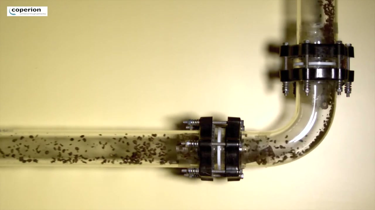
Dense Phase Conveying of Coffee Beans
Coperion shows dense phase conveying applied to coffee beans, where the point of the method is to move a fragile product without damaging it.
Total reach: 7,826

Coperion
E-finity Continuous Dense Phase Conveying
Coperion presents E-finity, a continuous dense phase conveying system for fragile granular and pelleted materials that monitors pressure and corrects the airflow during the run.
Total reach: 1,784
Magnum Systems
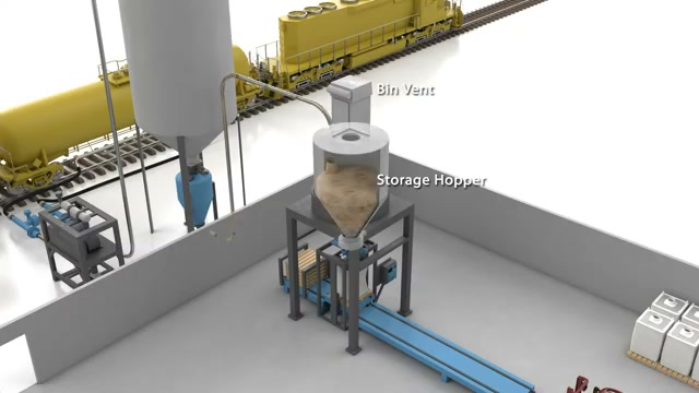
Dense Phase Conveying Process Flow Animation
Magnum Systems shows in a short animation how material travels through a dense phase line in slugs rather than as a continuous stream.
Total reach: 1,672
Magnum Systems
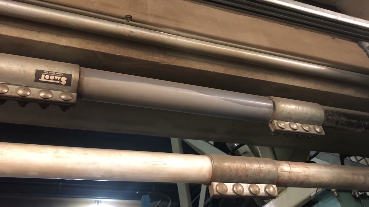
Dense Phase Conveying in the Test Laboratory
Magnum Systems shows dense phase pneumatic conveying running in its test laboratory in Kansas City.
Supplier discovery
Companies demonstrating Dense Phase Conveying
Frequently asked questions
Which trial results confirm that a powder can run in dense phase
Representative trials should show a stable dense-phase flow mode, an acceptable pressure trace, reliable restart and acceptable wear or product damage for the intended pipe size and route.
Which route features deserve special attention in dense phase
Vertical lift, bends, boosters, valves, reductions and the receiver entry can destabilize plugs or accelerate material, so each feature should be included in the tested configuration.
Can low average velocity guarantee gentle handling
No. Sliding contact, unstable plugs, local acceleration and receiver impact can still damage the product even when average line velocity is low.
Related content
Continue exploring
Move from this page to the companies, videos and technical topics that add useful context.