
Guide
Pneumatic Conveying System Design Guide
Answer in brief
A reliable pneumatic conveying design starts with representative material testing and a complete process duty. The conveying regime, pressure or vacuum arrangement, feed method, pipe route, air mover, receiver, filtration, controls, and protection concept are then selected as one system.
Capacity alone is not enough: the design must also control product damage, wear, segregation, dust, cleaning, energy use, and recovery from abnormal operation.
By Editorial Team · Published July 14, 2026 · Updated July 26, 2026

Sponsored visibility
Featured videos for this topic
Paid placements are clearly marked and remain separate from the editorial related-video selection.
Pneumatic conveying appears simple because the route is a pipe, yet the transported phase is a bulk solid whose behavior changes with air flow, pressure, moisture, particle size, and handling history.
A successful design cannot be copied from a liquid line calculation or selected from throughput alone. It needs a documented design basis, representative material data, a suitable flow regime, and verification across the expected operating range.
Define the complete conveying duty
The design basis should describe where material comes from, where it must go, how often it moves, and what condition must be preserved. Average capacity is only one input. Peak capacity, batch size, startup frequency, source level, destination pressure, available cycle time, and future expansion can all change the equipment choice.
The route must be defined in three dimensions. Horizontal distance, vertical lift, bend count, bend radius, flexible connections, diverters, destination elevation, and available straight pipe all affect pressure loss and particle behavior. A short route with many bends can be more demanding than a longer route with gentle geometry.
Minimum process information
- Required average and peak solids flow.
- Batch size, cycle time, and operating schedule.
- Source and destination vessel conditions.
- Pipe length, lift, bends, branches, and diverters.
- Permitted product damage, segregation, and contamination.
- Cleaning, hygiene, containment, and changeover requirements.
- Ambient and process temperature, humidity, and hazardous area conditions.
- Utility limits for electrical power, compressed air, and process gas.
Characterize the bulk solid
A material name alone is not a design property. Two grades sold under the same general name can have different fine content, moisture, particle shape, or surface condition. These differences can change feeding, pickup, pressure drop, electrostatic charging, and the ability to sustain dense phase flow.
Useful laboratory data include particle size distribution, particle density, loose and compacted bulk density, moisture range, cohesion, permeability, air retention, and deaeration behavior. Attrition sensitivity and abrasiveness matter when product value or component life is at risk. Chemical compatibility, temperature, combustibility, minimum ignition energy, and other relevant hazard data belong in the same design basis.
The Geldart groups are a useful first description of fluidization behavior, but they are not a complete conveying design method. Current research continues to examine how bulk density, particle size, fine content, permeability, and air retention affect the feasible mode. When a powder sits near a classification boundary, pilot conveying remains more dependable than classification alone.
Select the conveying regime
Dilute phase conveying keeps most particles suspended in the gas. It is widely applicable and can support continuous transfer with relatively simple feeding arrangements. The higher velocity can increase particle breakage, segregation, noise, and wear, especially at bends.
Dense phase conveying moves a greater concentration of solids at lower velocity. Depending on material behavior, flow can take the form of strands, dunes, slugs, plugs, or a fluidized bed; published reviews describe these regimes in detail. Dense phase can reduce attrition and wear, but it requires a material that forms a stable regime and an equipment concept that controls pressure, feed, and line clearing.
The dilute-or-dense decision should be expressed as an operating window rather than a label. The design team needs to know the minimum stable condition, the maximum useful throughput, the effect of changing material, and the response to startup and shutdown. A system that works at one test point but plugs during turndown is not robust.
Choose pressure or vacuum
Pressure systems place the air mover upstream and push gas and solids toward the destination. They can suit longer routes and multiple destinations. Material must enter against the conveying pressure, so the feed device and gas leakage need careful treatment.
Vacuum systems place the air mover after the receiver and draw material from the pickup point. They can collect from several sources and can support containment because leakage tends to move inward. The receiver, filter, discharge device, and air mover must handle the required vacuum and gas volume.
Some duties combine pressure and vacuum in separate stages. The choice rests on source access, destination arrangement, leakage direction, route length, required pressure difference, filtration, and maintenance access. It is separate from the choice between dense and dilute phase.
Establish the conveying air requirement
The gas flow must maintain the intended solids regime throughout the route. Too little gas can allow deposition, unstable flow, and blockage. Too much gas wastes energy and can increase wear or attrition. The relevant gas density changes with pressure and temperature, so standard volume and actual volume must not be confused.
Pressure loss includes the acceleration of solids, gas friction, solids friction, elevation, bends, fittings, filters, receivers, and the feed or discharge boundary. Published correlations, collected for example in the Pneumatic Conveying Design Guide, can support early design work, particularly for established dilute phase duties.
Their assumptions and material range must be understood. Dense phase design is often more dependent on test data and supplier experience because the flow pattern can change abruptly.
Design material feeding and pickup
The feeder establishes how solids enter the line and strongly influences stability. A rotary airlock can meter material into a dilute pressure line while limiting pressure leakage. A screw or controlled valve can feed certain vacuum systems. Dense pressure systems often use a pressure vessel with a defined fill, pressurize, convey, and depressurize cycle. Continuous dense phase arrangements use specialized feeding equipment.
The feed rate must match the available conveying air. Flooding the pickup can choke the line even when the downstream pipe is correctly sized. The pickup geometry should introduce solids in the direction of flow and provide sufficient acceleration distance before the first major disturbance.
Design the pipeline as a process component
Pipe diameter affects velocity, pressure loss, and the stable capacity range. Oversizing is not automatically conservative, because velocity can fall below the condition needed to transport solids. Undersizing can create excessive velocity, pressure drop, wear, and product damage.
Bends deserve special attention. Particles change direction through contact with the bend wall and interaction with the gas. Bend radius, geometry, orientation, material, surface, and replaceable wear protection all influence attrition and life. The route should avoid unnecessary direction changes and provide access to likely inspection points.
Thermal expansion, pipe supports, vibration, static charge, and forces during plugs or pressure transients also belong in mechanical design. Flexible hose can solve an access problem but may introduce wear, grounding, hygiene, or pressure limitations.
Partner with powderbulkvideos.com
Put your expertise beside the decisions engineers are making.
Connect a relevant company profile and technical video portfolio with clearly labelled visibility on this topic.
Size the receiver and filtration system
The destination must separate solids from the conveying gas without excessive product carryover or filter loading. Receiver volume, inlet geometry, filtration area, cleaning method, and discharge equipment should match the solids rate and gas flow. A receiver that accepts the solids but cannot release the air will create pressure and capacity problems.
Filter cleaning air, differential pressure measurement, access, containment, and safe element change are part of the design. Hygienic duties may require particular surface finishes, drainability, inspection access, and validated cleaning procedures. Potent or hazardous materials can require additional containment and secondary filtration.
Engineering visual guide
How the system behaves
These conceptual diagrams connect the operating principle, equipment internals and engineering review points. They are explanatory and not fabrication drawings or a substitute for project-specific calculations.
Engineering infographic
System architecture and interfaces
Conceptual system architecture and interface map for Pneumatic Conveying; use it to structure an engineering review, not as a fabrication drawing or project-specific design.
Select the air mover on the system curve
The blower, compressor, fan, or vacuum pump must deliver the required flow at the calculated pressure difference. Selection at free air flow is meaningless for the actual duty. The design should consider turndown, temperature rise, inlet conditions, filtration, relief, noise, and efficiency.
Variable speed control can adjust gas flow, but the control range must remain inside the stable conveying window. Reducing speed to save energy without monitoring solids behavior can create deposition and blockage. Instrumentation should support both efficiency and reliability.
Engineering infographic
Engineering design workflow
Conceptual engineering design workflow for Pneumatic Conveying; use it to structure an engineering review, not as a fabrication drawing or project-specific design.
Build a useful control strategy
A conveying sequence coordinates source availability, destination capacity, valves, feeder, air mover, filter cleaning, and line clearing. Permissives should prevent transfer toward a full or unavailable receiver. Interlocks should respond to abnormal pressure, loss of air flow, valve position, feeder faults, and filter restriction.
Useful measurements include pressure at selected points, receiver differential pressure, gas flow, vessel level, feeder speed, cycle time, motor load, and temperature. Trends are often more informative than a single alarm.
A gradual rise in pressure or cycle time can reveal buildup, filter restriction, wear, or a material change before capacity is lost. Repeated high-pressure trips, longer receiver cycles, rising filter load, frequent bend replacement, and increasing fines deserve the same attention as total downtime.
Address combustible dust and process safety
Pneumatic conveying can disperse fine combustible material and connect several vessels through pipework. Hazard assessment must consider ignition, electrostatic charging, frictional heating, foreign material, fire propagation, explosion pressure, and isolation between connected equipment.
Depending on the material, jurisdiction, and arrangement, protection can involve bonding and grounding, ignition control, explosion relief, suppression, isolation, pressure containment, inert gas, and validated shutdown logic. HSE guidance also emphasizes adequate air removal at receiving vessels, pressure monitoring, and level detection to avoid overfilling. OSHA identifies pneumatic conveying among processes that require evaluation for combustible dust hazards.
Use testing to reduce design uncertainty
A representative test should use material from the expected production range and reproduce important route features. Tests can establish stable capacity, pressure drop, gas demand, product damage, segregation, wear tendency, filter behavior, and restart performance.
Scaleup needs clear similarity criteria and engineering judgment. A short transparent test line cannot reproduce every industrial bend, lift, or cycle. The final design should document how test results were transferred to the plant route and where safety margins were applied.
Commission against measurable acceptance criteria
Commissioning should prove more than one nominal throughput point. It should cover startup, normal transfer, turndown, shutdown, line clearing, destination change, and recovery after a controlled interruption. Product quality, capacity, energy, filter pressure, dust containment, and equipment temperature should be recorded.
Operators need an operating window and a troubleshooting sequence. Increasing air flow is not a universal cure.
A blockage can result from feed surges, wet material, filter restriction, air leakage, valve timing, buildup, or a route obstruction. The diagnosis should use trends and physical findings.
Engineering infographic
Verification and acceptance checklist
Conceptual verification and acceptance checklist for Pneumatic Conveying; use it to structure an engineering review, not as a fabrication drawing or project-specific design.
Design review checklist
- Confirm that the material sample represents normal and difficult production conditions.
- Verify the capacity, route, lift, bends, sources, and destinations.
- Document product quality, hygiene, containment, and safety limits.
- Define the intended flow regime and stable operating window.
- Check feed control, pickup geometry, and line acceleration.
- Calculate pressure loss for the complete route and receiver.
- Select the air mover at the required flow and pressure.
- Verify receiver air handling, filtration, and discharge capacity.
- Review mechanical wear, supports, grounding, and access.
- Complete the dust hazard and protection review.
- Define controls, alarms, interlocks, and recovery sequences.
- Agree measurable commissioning and product acceptance criteria.
Hand over the design basis as an operating document
The final design basis should not disappear into a calculation file. Hand over the representative material data, operating envelope, route definition, pressure budget, selected flow regime, and the assumptions that still depend on site verification. Identify the instruments used to confirm each important assumption and the condition that requires engineering review.
Link the cause-and-effect matrix to practical recovery instructions. Operators need to know why feed stops on high pressure, what a rising filter differential pressure means, whether a line may be restarted with material inside, and which isolation steps precede access. Maintenance teams need the reference pressure, flow, cycle-time, and product-quality results from commissioning.
Manage change after acceptance
A pneumatic conveyor can be technically unchanged while its duty moves outside the validated envelope. A new powder supplier, greater fine content, higher moisture, an added bend, different filter media, or a faster feeder can alter flow behavior and pressure demand. Define which changes require a calculation review, a controlled trial, or a new hazard assessment.
The trend records described under the control strategy become the early-warning system here. Agree during handover who owns those records and how often they are reviewed, so deterioration is caught before nameplate capacity is lost.
Frequently asked questions
What information is needed to design a pneumatic conveying system?
The design needs representative material properties, required capacity, the complete pipe route, source and destination conditions, product quality limits, cleaning requirements, utilities, and safety data. Material name and throughput alone are not sufficient.
How is pneumatic conveying pipe diameter selected?
Diameter is selected by balancing velocity, pressure loss, stable solids flow, wear, and capacity across the route. Oversizing can allow deposition, while undersizing can create excessive velocity and pressure demand.
When is pilot testing required?
Testing is especially valuable for dense phase duties, unfamiliar powders, fragile or abrasive products, uncertain scaleup, and applications with strict product quality or reliability requirements.
What causes a pneumatic conveying line to block?
Common causes include unstable feeding, insufficient gas flow, excessive solids loading, wet or changed material, filter restriction, air leakage, poor pickup geometry, buildup, and route obstruction.
How should system performance be accepted?
Acceptance should cover capacity, product quality, pressure, energy, filter behavior, containment, startup, turndown, shutdown, line clearing, and recovery after an interruption.
Related content
Continue exploring
Move from this page to the companies, videos and technical topics that add useful context.
Companies


Videos

Hosokawa Solids Solutions GmbH
Hosokawa Solids Solutions: Solids Puls Pneu Conveying System
Hosokawa Solids presents the Solids Puls Pneu plug-conveying system with bypass, impulse-valve and relay-station components.
Total reach: 70,221

HS Umformtechnik GmbH
HS Umformtechnik Company Video
HS Umformtechnik presents large-radius pipe bends, pipe couplings and branch pipes for pneumatic conveying systems.
Total reach: 6,262
Qlar
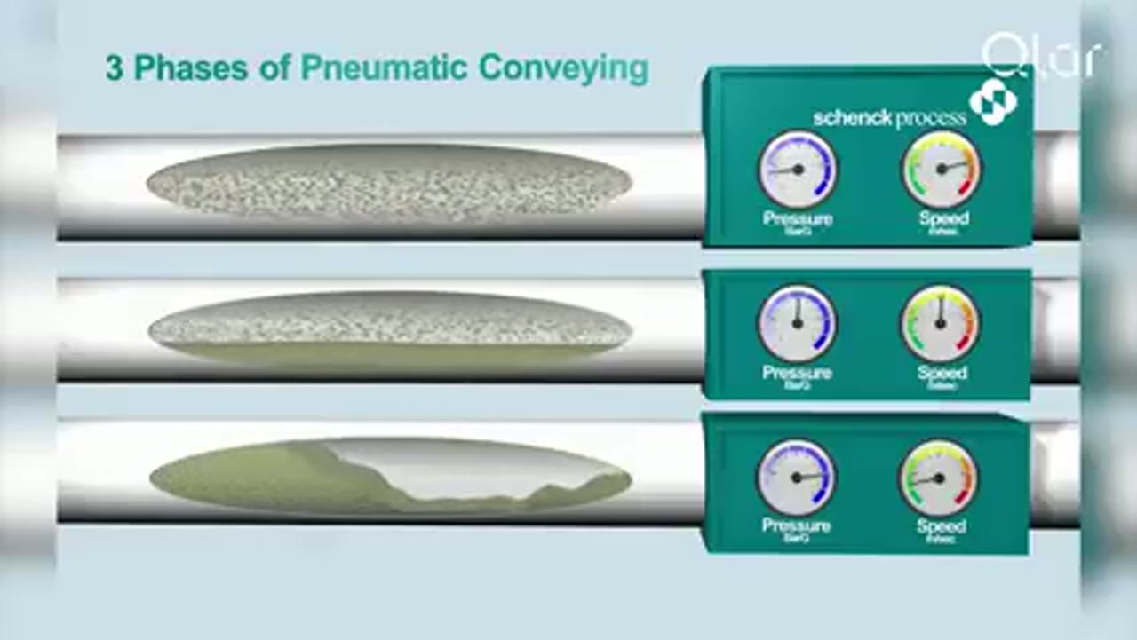
Pneumatic Conveying Explained: The 3 Key Phases of Dense Phase Conveying
Qlar explains the three phases of dense phase pneumatic conveying and where each one fits when powders, granules and bulk solids have to move without being damaged.

VAC-U-MAX
VAC-U-MAX: 10 Critical Design Factors to Consider When Designing Vacuum Conveying Systems
VAC-U-MAX presents ten design factors for vacuum conveying, including pickup, material behavior, route, receiver, filtration, discharge and controls.
Total reach: 10,990

VAC-U-MAX
VAC-U-MAX: Signature Series Packaged Vacuum Conveying Systems
With over 65 years of experience in pneumatic conveying and more than 10,000 powders and granular materials handled, VAC-U-MAX packages its Signature Series vacuum conveying systems as complete units: receiver, UL-listed controls, convey hose, filters, and vacuum producer.
Total reach: 10,588
Powder Process-Solutions
Pressure Dilute Phase
The Powder Process-Solutions animation shows a positive-pressure dilute-phase arrangement in which a gas stream pushes suspended material through the conveying line toward the receiver.
Total reach: 92,214