
Guide
Vacuum Conveying System Selection & Design Guide
Answer in brief
Select a vacuum conveying system from measured material behavior and a written duty, not from pipe diameter alone. The design basis states the required rate, route, lift, pickup method, destination pressure, cleaning expectation and hazard controls. Test with representative powder whenever the material is cohesive, fragile, abrasive, electrostatic or otherwise hard to predict.
By Editorial Team · Published July 15, 2026 · Updated July 26, 2026

A vacuum conveying design begins with a written duty. Define what must move, from where, to where, at what rate and under which quality and safety constraints. Capacity calculations without this context create false precision.
1. Characterize the powder
Record bulk density, particle size distribution, cohesion, moisture, temperature, abrasiveness, friability and electrostatic behavior. Use test data from representative material when flow is uncertain.
Include realistic variation. A powder can change after storage, transport or a change in supplier. State whether samples are loose, aerated, compacted or conditioned, because that state affects pickup and feed stability.
2. Define pickup and destination
Describe whether material comes from a bag, drum, bulk bag, hopper or process machine. At the destination, state pressure, available headroom, batch sequence and how the receiver will discharge.
Pickup design controls how solids enter the air stream. A bag dump, a lance in a drum and a closed process outlet do not present the same solids-to-air ratio. For every pickup point, document material condition, required batch or continuous rate, available air entry, connection geometry and operator task. Define whether sources operate one at a time and how an unused branch is isolated.
The review should also cover bridging, flooding, liner collapse, dust at manual connections and foreign material entering the line. A pickup control that works with an open bag may choke when connected to a flood-fed hopper.
False air: map leakage paths through couplings, flexible hose, valves and receiver discharge. The design should show how much of the vacuum source capability is reserved for useful transport and how loss of sealing will be detected.
Engineering visual guide
How the system behaves
These conceptual diagrams connect the operating principle, equipment internals and engineering review points. They are explanatory and not fabrication drawings or a substitute for project-specific calculations.
Engineering infographic
System architecture and interfaces
Conceptual system architecture and interface map for Vacuum Conveying; use it to structure an engineering review, not as a fabrication drawing or project-specific design.
3. Map the route
Document horizontal distance, vertical lift, bends, flexible sections and restrictions. The route influences pressure loss, conveying velocity, wear and the risk of material settling.
Use the proposed installation route, not a straight-line distance. Identify bend radius, pipe material, joints, elevation changes and any section that must be removed for cleaning. Changes made during installation should be checked against the design basis.
4. Size the receiver, separation and filtration
The receiver must separate powder from air without unacceptable carryover. Its volume must also hold incoming solids between discharge events while leaving the separation and filter zones functional, so check peak solids arrival, not only average plant rate. Define the pressure equalization, filter cleaning and discharge sequence, and confirm the downstream process can accept each release.
Filter performance affects both capacity and product retention. Select filter area, media and cleaning method for particle size, chemistry, temperature, moisture, hygiene and the expected dust loading. Include the clean and expected loaded differential pressure in the system curve, and state the alarm and action for rising restriction as well as the protection against product reaching the vacuum producer.
Define the inspection method and replacement criteria up front. Where contamination matters, consider how a used filter is removed and contained.
Machine cutaway
Define the receiver boundary before sizing the system
Representative vacuum receiver showing the solids inlet, separation volume, filter elements, clean-air plenum and sealed discharge. It explains the receiver boundary rather than the complete conveying system.
5. Match the air mover to the operating envelope
The air mover must provide the required flow at the pressure loss of the complete system. Review turndown, noise, heat, maintenance, utility demand and the consequences of air leakage. A nominal motor rating alone does not describe conveying performance.
Partner with powderbulkvideos.com
Put your expertise beside the decisions engineers are making.
Connect a relevant company profile and technical video portfolio with clearly labelled visibility on this topic.
6. Integrate controls and safety
Define feed permissives, level control, filter cleaning, discharge sequence and fault recovery. For combustible or hazardous dust, complete the site-specific risk assessment and include connected equipment.
OSHA identifies electrostatic discharge, heat, sparks, foreign material and connected separators as possible concerns in pneumatic transfer. The appropriate controls depend on the material and installation. They cannot be inferred from the use of negative pressure alone.
7. Design cleaning and maintenance
State whether cleaning is dry, wet, manual, automated or based on product dedication. Identify access to pipe, receiver, filter, seals and discharge equipment. Define inspection points and the maximum time allowed before residues become harder to remove.
Handover should also set the maintenance records: hose inspection criteria, seal and valve checks, filter replacement limits, safe receiver access and the expected baseline for vacuum level and cycle time. These records preserve the tested operating envelope after commissioning.
8. Test the complete duty
Measure rate, stability, pressure, filter behavior, residual material, product condition and restart performance. Use representative powder on the actual or equivalent hose, lift and bends, and test the longest or most restrictive pickup, the required turndown and the difficult material condition. Record the tested configuration so results are not applied to a materially different route.
Run repeated cycles that include normal startup, a controlled stop, filter cleaning and receiver discharge. Record receiver vacuum, filter differential pressure, conveying time and batch mass or continuous rate. Where batch accuracy matters, reconcile the mass charged with the mass received and retained.
Abnormal cases: include a blocked pickup, a full destination, a failed branch valve or an interrupted cycle as appropriate to the duty. Verify that feed stops, pressure is released in a controlled way and operators can identify the cause without opening equipment prematurely. The restart method should not depend on uncontrolled hose disconnection or repeated maximum-vacuum attempts.
9. Record the acceptance decision
The final report should list the tested material, route, settings, observations, deviations and acceptance criteria. Separate confirmed results from supplier estimates. This record becomes the baseline for commissioning, maintenance and future process changes.
Engineering infographic
Engineering design workflow
Conceptual engineering design workflow for Vacuum Conveying; use it to structure an engineering review, not as a fabrication drawing or project-specific design.
Engineering infographic
Verification and acceptance checklist
Conceptual verification and acceptance checklist for Vacuum Conveying; use it to structure an engineering review, not as a fabrication drawing or project-specific design.
Review changes after commissioning
Capacity and reliability can change when the powder supplier, route, filter, pickup tool or production sequence changes. Establish which changes require engineering review or repeat testing, and assign an owner and a review interval for those records.
Trend cycle time, vacuum level, filter differential pressure and maintenance findings where the values are available. A gradual loss of performance can then be investigated before it becomes a blockage, quality deviation or unplanned shutdown.
Frequently asked questions
What data is needed to size a vacuum conveyor?
At minimum, provide the powder, bulk density, particle size, required rate, pickup condition, route, lift, destination, duty cycle and cleaning requirements.
When should conveying tests be used?
Testing is valuable when the powder is cohesive, fragile, abrasive, electrostatic, moisture sensitive or unlike materials covered by reliable prior data.
How is a system accepted?
Use documented criteria for rate, cycle stability, filter behavior, discharge, residual material, product condition, controls and safe recovery from faults.
Related content
Continue exploring
Move from this page to the companies, videos and technical topics that add useful context.
Companies
Videos

Airlock
Airlock: Air only Diverter Valve for Pressure and Vacuum
The video explains an Airlock bypass valve for routing conveying air in pressure and vacuum systems. It shows an air handling component, not a valve intended to divert powder through alternate product lines.
Total reach: 20,357
Volkmann GmbH
Suction lance for powder feeding
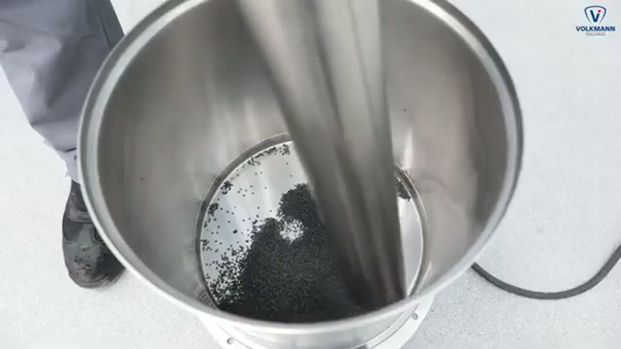
The Volkmann video shows powder being introduced from a drum or container through a suction lance into a vacuum conveying line. It shows the pickup boundary and the need to admit material and conveying air in a controlled way. Capacity and suitability depend on the powder and need a conveying trial with the actual material.
Total reach: 1,772
Products
Technologies
Applications
- Chemical Powder Repackaging and Batching
- Feeder Refill from Pneumatic Conveying
- Gentle Ingredient Transfer from Gaylord Boxes
- Hygienic Vacuum Conveying for Food and Pharma
- Inline Screening in Conveying and Processing Lines
- Polysilicon Powder Reclamation
- Vacuum Conveying for Battery Powder
- Vacuum Conveying from Bulk Bags to Process Equipment