
Technology guide
Vacuum Conveying
Answer in brief
Vacuum conveying pulls bulk material through a closed line toward a receiver placed ahead of the vacuum source. It fits layouts where several pickup points feed one destination, and because leakage runs inward it can help keep dust at the source.
Capacity comes from the pressure difference that is still available after pickup, pipe, receiver, and filter losses have taken their share.
By Editorial Team · Reviewed July 14, 2026 · Updated July 26, 2026

A vacuum conveying system creates negative pressure at the receiver and pulls gas through the pickup point. Material enters the moving gas, travels to the receiver, separates from the gas, and discharges into the next process. The vacuum source sits downstream of filtration and should never see product in normal operation.
Where vacuum conveying fits
Vacuum suits layouts where material is collected from several sources and delivered to one receiver: bags, drums, hoppers, process equipment, or local collection points. Leakage tends to move inward, so the arrangement can support containment at the source even when connections are imperfect.
That is not the same as a dust-free system. Containment and cleaning have to cover the complete handling task, not only the transfer itself.
Vacuum does not define the conveying phase
A vacuum system can run in dilute or dense phase when the material, pressure difference, feeding, and equipment support that regime. Dilute vacuum conveying is common and keeps particles suspended. Dense vacuum conveying uses a higher solids concentration and can reduce particle velocity for suitable material.
The pressure difference available under vacuum has a hard practical limit. Filter restriction, receiver pressure loss, pipe friction, elevation, and material acceleration each take a share of it. Route length and capacity therefore have to be evaluated together rather than one after the other; published design methods for dilute-phase conveyors work through these loss terms in sequence.
Pickup, feed control, and false air
Material entry needs both solids and air. An unrestricted opening can admit too much material and choke the line. A pickup wand, feed hopper, valve, screw, or engineered nozzle controls the ratio and directs solids into the pipe.
Air that enters through pickup tools, open connections, worn seals, and the receiver discharge still becomes part of the gas flow, but it does not necessarily move product. Too much of this false air lowers the vacuum reaching the intended pickup and raises filter duty. Too little air at the pickup floods the line with solids.
Commissioning should therefore fix two things: the pickup setting, and the acceptable leakage state of the complete system. Where several sources share one receiver, only the intended route stays open unless simultaneous pickup was designed and tested. Valve position feedback and a clear sequence keep an unused branch from becoming a large air leak.
Flexible hose gives useful access, but diameter, bend radius, wear, static control, cleanability, and collapse under vacuum all need review. Hose condition, couplings, and gaskets belong in routine inspection. The pickup should also avoid drawing in foreign objects that could damage valves, filters, or the air mover.
Engineering infographic
Operating sequence
Conceptual operating sequence for Vacuum Conveying; use it to structure an engineering review, not as a fabrication drawing or project-specific design.
Receiver and filter design
The receiver separates solids from the conveying gas. Inlet geometry, volume, filtration area, and the cleaning system have to handle peak gas and solids flow. Fine or cohesive powder can blind filter media and raise differential pressure, and a rising pressure loss directly reduces available conveying capacity.
Filter selection depends on particle size, chemistry, temperature, hygiene, and hazard. Potent material may require contained filter access and secondary filtration. Food and pharmaceutical duties can call for cleanable surfaces, inspection access, and documented cleaning.
The receiver also has to keep product out of the vacuum producer during stable conveying, during filter cleaning, and in an overfill event. Differential pressure shows filter restriction; a level or sequence limit protects against accumulated solids reaching the filter. Consider what a torn filter or a failed discharge seal would do. Secondary filtration or monitoring needs a defined inspection and response plan, and a pump that tolerates some dust does not lower the separation requirement.
Machine cutaway
Inside a vacuum conveying receiver
Representative receiver cutaway showing the solids inlet, separation zone, filter elements, clean-air plenum and sealed discharge into downstream process equipment. Actual inlet, filter-cleaning and outlet arrangements vary.
Discharge and sequencing
Batch vacuum receivers usually alternate between conveying and discharge. During conveying, the discharge closes and vacuum builds. After transfer, the receiver isolates from the vacuum source, returns toward atmospheric pressure, and releases material. Discharge should not start before the receiver is in that intended pressure state.
Continuous arrangements can use an airlock or a twin receiver sequence. The discharge device must limit unwanted air entry and avoid damaging product. A full downstream vessel or a closed valve should block the next conveying cycle.
Selecting the vacuum source
Vacuum pumps, blowers, fans, and ejectors offer different combinations of flow, vacuum, efficiency, maintenance, and contamination tolerance. Selection has to use the required operating point, not free flow. The analysis covers inlet condition, filter loss, leakage, temperature, turndown, noise, and duty cycle.
A recent experimental study compared blower and ejector based vacuum transfer for one surrogate powder. It shows that the method of vacuum generation can influence pressure, saltation, energy, and particle response. Those results should not be carried across to another material without equivalent testing.
Controls and diagnostics
- Receiver vacuum and filter differential pressure.
- Conveying and discharge cycle time.
- Destination level and valve position.
- Vacuum source temperature and motor load.
- Gas flow where stable capacity or energy is critical.
Longer cycle time can point to filter restriction, leakage, worn seals, a material change, buildup, or a partly blocked pickup. Record the baseline vacuum, cycle time, and filter differential pressure at acceptance. Trended against that baseline, these changes become visible well before the system stops meeting capacity.
Containment, cleaning, and dust safety
Vacuum reduces outward leakage during normal transfer, but combustible dust hazards remain. Electrostatic charging, foreign material, frictional heating, fire propagation, and connected receivers all require assessment. Bonding, grounding, ignition control, isolation, explosion protection, and safe filter service depend on the actual dust and the actual system.
Exposure typically happens outside the transfer step: opening bags, disconnecting hose, cleaning filters, emptying the receiver. Watch the complete task during acceptance. Define how residual material is recovered, how components are isolated, and how a contaminated filter is handled.
For hygienic service, inspect dead spaces, seals, hose construction, and access rather than trusting stainless-steel appearance. Demonstrate the cleaning method and the evidence used to release the system for the next product.
Selection checklist
- Characterize the material and its most difficult operating condition.
- Define all pickup points, route geometry, and destination duty.
- Select dilute or dense operation based on evidence.
- Control solids and air entry at each pickup.
- Size the receiver and filter for peak gas and solids flow.
- Verify discharge timing and downstream capacity.
- Select the vacuum source at the real system operating point.
- Complete containment, cleaning, and dust hazard reviews.
Engineering infographic
Functional zones and interfaces
Conceptual functional zone schematic for Vacuum Conveying; use it to structure an engineering review, not as a fabrication drawing or project-specific design.
How to select Vacuum Conveying
- Define the powder or bulk solid, with its relevant physical and safety data.
- State the required transfer rate, operating schedule, and acceptable residual material.
- Map horizontal distance, vertical lift, bends, pickup points, and destinations.
- Set the limits for product degradation, wear, contamination, and containment.
- Record available utilities, filtration, controls, cleaning, and maintenance access.
Partner with powderbulkvideos.com
Place your video in the engineering context buyers are researching.
Use a relevant company profile and technical video to demonstrate this technology before engineers reach the supplier shortlist.
Engineering infographic
Engineering review envelope
Conceptual engineering review envelope for Vacuum Conveying; use it to structure an engineering review, not as a fabrication drawing or project-specific design.
Continue your research
Vacuum Conveying guides and answers
Specialist Technology
Chemical Repackaging and Batching of Powders
Chemical repackaging (repacking) and batching of powders: contained transfer, accurate weighing and lot traceability — equipment and design guidance.
Specialist Technology
Gentle Ingredient Transfer from Gaylord Boxes
How to move fragile food ingredients from Gaylord boxes with controlled tilting, stable pickup and low-damage vacuum conveying, and how to verify results.
Specialist Technology
Hygienic Vacuum Conveying for Food and Pharma
Hygienic vacuum conveying for food and pharma: cleaning methods, cross-contamination control, qualification and the acceptance tests each project needs.
Specialist Technology
Polysilicon Powder Reclamation and Transfer
Polysilicon powder reclamation recovers fine silicon from bounded sources, moves it in a closed system and releases it against a defined specification.
Specialist Technology
Vacuum Conveying FAQ
Vacuum conveying FAQ: how negative-pressure transfer works, why systems lose capacity, which powders need conveying tests, and how to assess dust hazards.
Specialist Technology
Vacuum Conveying System Selection & Design Guide
Select a vacuum conveying system from measured powder behavior and a defined duty. This guide covers pickup design, routing, filtration, testing, and safety.
Specialist Technology
Vacuum Conveying for Battery Powder
Vacuum conveying design for battery powders: contamination control, moisture limits, filters, grounding, cleaning, and acceptance testing with real material.
Specialist Technology
Vacuum Conveying from Bulk Bags to Process Equipment
Vacuum conveying from bulk bags to process equipment: coordinate bag discharge and pickup, protect the receiver sequence, and prove the transfer in testing.
Popular on powderbulkvideos.com
Popular Vacuum Conveying videos

Airlock
Airlock: Air only Diverter Valve for Pressure and Vacuum
The video explains an Airlock bypass valve for routing conveying air in pressure and vacuum systems. It shows an air handling component, not a valve intended to divert powder through alternate product lines.
Total reach: 20,357
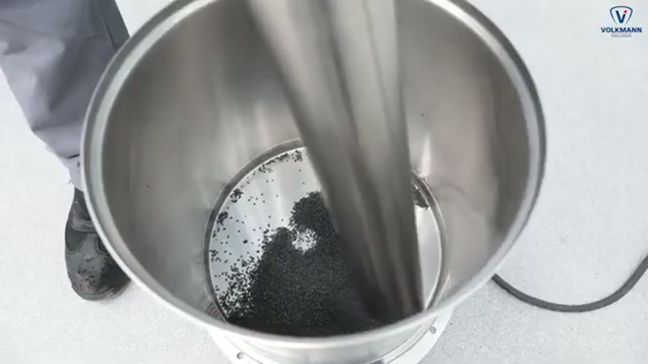
Volkmann GmbH
Suction lance for powder feeding
The Volkmann video shows powder being introduced from a drum or container through a suction lance into a vacuum conveying line. It shows the pickup boundary and the need to admit material and conveying air in a controlled way. Capacity and suitability depend on the powder and need a conveying trial with the actual material.
Total reach: 1,770
Supplier discovery
Companies demonstrating Vacuum Conveying
Frequently asked questions
Which components consume the available vacuum
Pickup losses, pipe and bend losses, solids acceleration, receiver pressure drop, and filter loading each take a share of the pressure difference the vacuum source provides.
Why does receiver design control vacuum-conveying capacity
The receiver has to separate solids from the gas, hold its filter within an acceptable pressure-drop range, and discharge without breaking the intended conveying cycle.
Does negative pressure remove combustible-dust risk
No. Ignition sources, electrostatic charging, connected equipment, and propagation paths still have to be assessed for the actual material and installation.
Related content
Continue exploring
Move from this page to the companies, videos and technical topics that add useful context.
Products
Technologies
Applications
- Chemical Powder Repackaging and Batching
- Feeder Refill from Pneumatic Conveying
- Gentle Ingredient Transfer from Gaylord Boxes
- Hygienic Vacuum Conveying for Food and Pharma
- Inline Screening in Conveying and Processing Lines
- Polysilicon Powder Reclamation
- Vacuum Conveying for Battery Powder
- Vacuum Conveying from Bulk Bags to Process Equipment