
Comparison
Vibratory Sieve vs Centrifugal Sifter
Answer in brief
Neither machine wins by default. A vibratory sieve presents powder to one or more vibrating screens and supports safety screening or grading; a centrifugal sifter uses rotating paddles inside a cylindrical screen for enclosed inline sifting or deagglomeration. Define the separation objective and feed condition first, then let containment, access and cleaning decide which concept goes to a representative trial.
By Editorial Team · Published July 17, 2026 · Updated July 26, 2026

Vibratory sieves and centrifugal sifters can both remove unwanted material or separate powder according to a screen aperture, yet they present the product to the mesh in different ways. A vibratory machine moves the screen assembly so material travels and stratifies across a screening surface.
A centrifugal sifter feeds powder into a cylindrical screen, where a rotating paddle assembly accelerates it against the mesh. Both sit in the wider size reduction and screening family.
That mechanical difference shapes residence, product presentation, oversize movement, enclosure, access and the way a process upset shows itself. It does not create a universal winner. The comparison below applies one engineering method to both technologies.
Define what “screening” must achieve
A screen aperture is only one part of the requirement. State first whether the machine must protect downstream equipment, remove occasional foreign material, break soft agglomerates, recover a usable fraction or produce multiple size cuts. These objectives require different tests and may lead to different screen arrangements.
Then define which stream matters. For a safety screen, the passing product may be the process output and retained material a reject that needs inspection. For grading, both fractions may be products with defined quality limits. A machine can move material successfully while failing the actual separation objective, so acceptance must measure the relevant fractions rather than rely on visual flow alone.
Engineering visual guide
How the system behaves
These conceptual diagrams connect the operating principle, equipment internals and engineering review points. They are explanatory and not fabrication drawings or a substitute for project-specific calculations.
Engineering infographic
Side-by-side operating principles
Conceptual side-by-side operating schematic for Screening & Sieving Systems; use it to structure an engineering review, not as a fabrication drawing or project-specific design.
Machine cutaway
Inside a centrifugal sifter
Conceptual centrifugal-sifter cutaway separating screened fines from retained oversize through independent enclosed outlets. Rotor, paddle, screen, feed and reject arrangements must be confirmed for the selected machine.
How each technology presents powder to the mesh
In a vibratory sieve, vibration moves the screen and influences how particles contact the aperture. Feed distribution, bed depth, vibration condition, screen tension and discharge geometry all shape the observed result. Configurations range from a single screening surface to multiple decks when the process needs more than one fraction, and the exact arrangement must be reviewed for the stated duty.
In a centrifugal sifter, a rotor and paddles move powder through a cylindrical screening zone. This enclosed inline principle is often evaluated for safety sifting or deagglomeration, where material can be fed continuously through a compact process interface. Rotor condition, feed consistency, screen state, oversize discharge and access for inspection are central to the review.
Whichever mechanism makes the shortlist, the test requirement stays the same: representative powder must reach a defined screen in a controlled condition, and the resulting streams must be measured against agreed criteria.
Decision matrix
| Selection question | Vibratory sieve | Centrifugal sifter |
|---|---|---|
| Material presentation | Powder travels across a vibrating screening surface | Rotating paddles present powder to a cylindrical screen |
| Separation arrangement to investigate | Direct safety screening or grading, including possible multi-deck configurations | Enclosed inline sifting or deagglomeration with passing and oversize outlets |
| Feed sensitivity | Distribution and bed depth influence access to the mesh | Consistent feed into the rotor and screen zone supports a stable operating state |
| Primary inspection focus | Screen surface, tension, seals, vibration behavior and discharge paths | Cylindrical screen, rotor and paddles, seals and oversize outlet |
| Typical upset to include in a trial | Screen blinding, uneven loading or loss of intended vibration | Feed surge, screen restriction, rotor loading or oversize accumulation |
| Measurements required | Mass balance, fraction quality, screen integrity, containment observations and cleanability with representative product |
The table asks different questions around the same objective. Neither technology achieves a finer cut, greater throughput or better product quality by principle; only a comparable test shows which one does. Supplier proposals should state the feed condition, aperture, screen construction, operating setup and acceptance method behind every performance statement.
Engineering infographic
Selection envelope
Conceptual selection envelope for Screening & Sieving Systems; use it to structure an engineering review, not as a fabrication drawing or project-specific design.
Powder behavior controls the usable screening area
Particle size distribution, shape, cohesion, moisture, electrostatic behavior and bulk density influence how powder reaches and passes an aperture. A nominally fine powder can form agglomerates that behave as larger particles. A free-flowing sample may spread readily, while a cohesive one can form a deeper bed or cover the mesh.
Record the state of the sample before testing. Storage time, compaction, temperature or a prior processing step can change that state. If the process includes deliberate deagglomeration, define how product quality will distinguish acceptable soft agglomerate breakup from unwanted particle damage.
Feed rate needs a range rather than one nominal value. A surge can reduce the time and open area available for separation, regardless of machine type. The upstream feeder, hopper or conveying discharge is therefore part of the screening duty.
Containment and displaced air belong in the layout
An enclosed housing does not by itself provide containment. Powder can be released at the inlet, passing-product outlet, oversize outlet, flexible connection, inspection cover or screen-change task. If pneumatic transfer feeds the machine, displaced and conveying air can add another interface that needs a controlled path.
A centrifugal sifter’s inline enclosure may fit a process that values a compact contained route, but its rotating internals and access points still require inspection. A vibratory sieve may offer direct access to its screening surface, but the surrounding seals, clamps and motion must suit the containment objective. Compare the real operating and maintenance tasks, not only the closed appearance of each housing.
Partner with powderbulkvideos.com
Put your expertise beside the decisions engineers are making.
Connect a relevant company profile and technical video portfolio with clearly labelled visibility on this topic.
Cleaning is a sequence, not a feature label
State whether cleaning means product recovery, routine dry clean, allergen or formulation changeover, wet cleaning, inspection, or release under a quality system. List every product-contact part and show how it is removed or reached. The review should cover screens, frames, paddles, rotor surfaces, seals, outlets and any flexible connection.
For a vibratory sieve, screen deck removal, seal placement and reassembly need a controlled method that protects the mesh and restores the intended clamping condition. For a centrifugal sifter, the cylindrical screen and rotor area need sufficient access for inspection and residue removal. Neither can be declared easier to clean without the exact configuration, cleaning method and acceptance criteria.
Integrity and maintenance can change the product decision
A damaged or incorrectly installed screen can compromise the intended separation. The inspection plan should define when screen condition is checked, what constitutes damage and how reassembly is verified. Where foreign-material control is critical, the response to a suspected breach must be defined before production starts.
Vibratory systems add motion-related checks around mounts, screen tension, clamps and the condition that produces the intended vibration. Centrifugal systems add checks around the rotor, paddles, clearances and drive condition. Service intervals depend on the selected machine; take them from the supplier’s documentation and operating experience.
Controls can help distinguish a stable process from an upset. Relevant signals may include upstream feed state, drive status, vibration condition, motor load, outlet availability or downstream level. The necessary sensors and alarm limits must be justified for the final arrangement rather than copied from a generic diagram.
Example machines and what to confirm
The Hapman Compact Sieve is a vibratory example; the Hanningfield Kwik-Sift is a centrifugal example. Both show the broad arrangement of feed, screen zone, outlets, access and installation interfaces.
Aperture, throughput, separation efficiency, cleanability, hazardous-area suitability and material compatibility depend on the configuration and the product. Review startup, shutdown and product changeover as well. Request current documentation for the exact proposed configuration.
Plan a representative comparison trial
Provide each supplier with the same material description, feed range, separation objective and required fractions. Agree the sample condition, aperture, test duration, startup method, sampling points and disposition of retained material. If the proposals use different screen areas or arrangements, make those differences visible rather than comparing one headline value.
During the trial, record mass entering and leaving each relevant stream, sample the passing and retained fractions, observe feed stability, and document any intervention. Include an upset or restart that reflects the real process. After the run, inspect the screen, seals and internal surfaces and record residual material and cleaning effort under the agreed method.
A useful acceptance report preserves the material lot, configuration, screen identity, operating settings, observations and deviations. It separates measured results from supplier estimates. Later changes in formulation, moisture, aperture, feed method or operating range should be reviewed against that baseline.
Engineering infographic
Failure and safety comparison
Conceptual failure and safety comparison for Screening & Sieving Systems; use it to structure an engineering review, not as a fabrication drawing or project-specific design.
Selection questions for the project team
- Is the duty safety screening, grading, deagglomeration or recovery?
- Which fraction is product, reject or material for investigation?
- What material variation and feed surges must the machine tolerate?
- How will displaced air, dust and oversize be handled?
- How are screen integrity, access, cleaning and correct reassembly verified?
- Which abnormal conditions must stop feed or trigger inspection?
- What measurements will demonstrate an acceptable separation?
The right choice is the technology whose tested configuration meets those requirements with a workable operating and maintenance sequence.
Frequently asked questions
What is the main difference between a vibratory sieve and a centrifugal sifter?
A vibratory sieve moves the screen assembly so powder travels across a screening surface. A centrifugal sifter uses rotating paddles inside a cylindrical screen to present powder to the mesh.
Which technology is better for safety screening?
Either may be considered. The decision depends on feed condition, required aperture, containment, fraction handling, screen-integrity controls, access and results from representative product testing.
Can a centrifugal sifter also deagglomerate powder?
Deagglomeration may be part of the stated duty, but the project must define acceptable breakup and confirm that the tested configuration does not cause unacceptable product change.
What should be inspected after a screening trial?
Inspect the screen, seals, clamps or mounting points, rotor and paddles where applicable, outlets and retained-product areas. Record screen identity, damage, residue and any intervention during the run.
Can a supplier video prove separation performance?
No. Aperture, throughput, separation efficiency, cleanability, compliance and suitability depend on the configuration and the product. Confirm them with a trial on representative product.
Related content
Continue exploring
Move from this page to the companies, videos and technical topics that add useful context.
Companies

Videos

HAZEMAG & EPR GmbH
HAZEMAG | Recycling | C&D Waste | 1946 – today
HAZEMAG & EPR GmbH designs, manufactures, installs and commissions plants for the cement & aggregate, minerals processing and recycling industries, combining equipment optimization expertise with beneficiation experience across the processing chain.
Total reach: 6,442
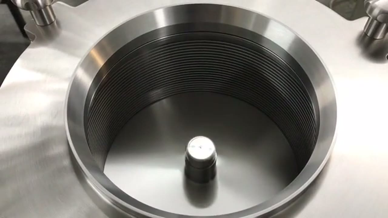
Hanningfield
Hanningfield Centrifugal Sifter (Kwik-Sift)
Hanningfield's Kwik-Sift video walks through centrifugal sifting — rotating assembly, cylindrical screen, and separate discharge paths for product and oversize.
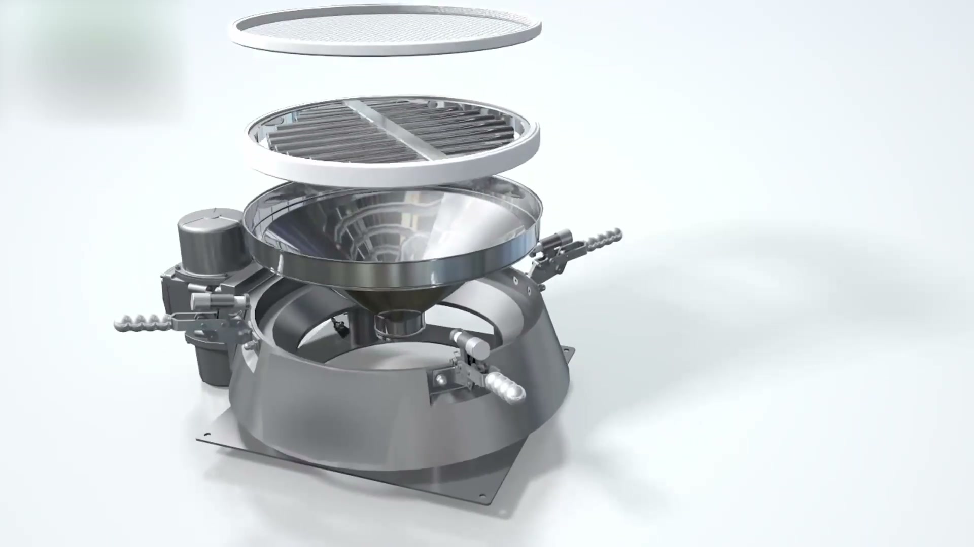
Hapman
Hapman Compact Sieve Animation
Hapman's animation shows a compact vibratory sieve mounted beneath a bulk bag unloader, screening powder before it enters the next process step. The sieve is a high-capacity, easy-clean option for restricted spaces.

RETTAR
RETTAR: 3D Radar Scanner
RETTAR presents its 3DPro2300 3D radar scanner in this video.
Total reach: 19,787